عضویت
عضویت  ورود اعضا
 راهنمای خرید


Accelnet R200 pages

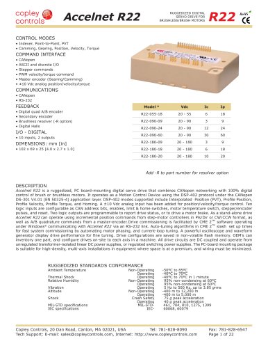
Accelnet R20
RUGGEDIZED DIGITAL
SERVO DRIVE FOR
BRUSHLESS/BRUSH MOTORS
R20
CONTROL MODES
• Indexer, Point-to-Point, PVT
• Camming, Gearing, Position, Velocity, Torque
COMMAND INTERFACE
• Stepper commands
RoHS
R
Single-ended or Differential selectable
• CANopen
• ASCII and discrete I/O
• ±10V position/velocity/torque command
• PWM position/velocity/torque command
• Master encoder (Gearing/Camming)
COMMUNICATIONS
• CANopen
• RS-232
• RS-422 (Optional)
FEEDBACK
• Digital quad A/B encoder
• Aux encoder / emulated encoder out
• Analog sin/cos encoder (-S versions)
• Brushless resolver (-R option)
• Digital Halls
I/O - DIGITAL
• 12 inputs, 3 outputs
DIMENSIONS: mm [in]
• 168 x 99 x 31 [6.6 x 3.9 x 1.2]
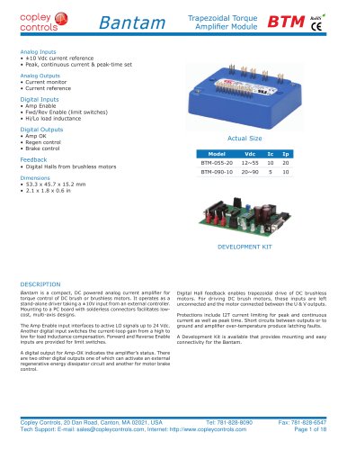
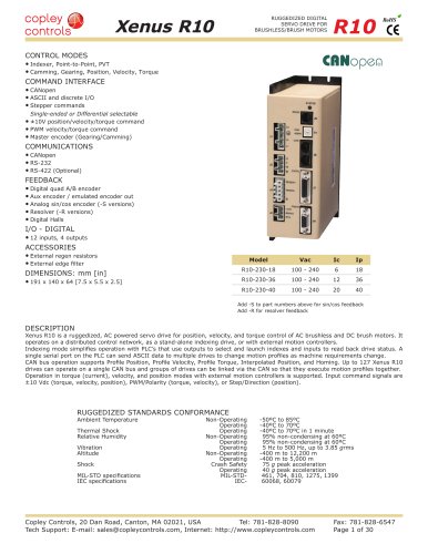
Model
Ip
Ic
Vdc
R20-055-18
18
6
55
R20-090-09
9
3
90
R20-090-18
18
6
90
R20-090-36
36
12
90
R20-180-09
9
3
180
R20-180-18
18
6
180
Add -S to part numbers above for sin/cos feedback
Add -R to part numbers above for resolver feedback
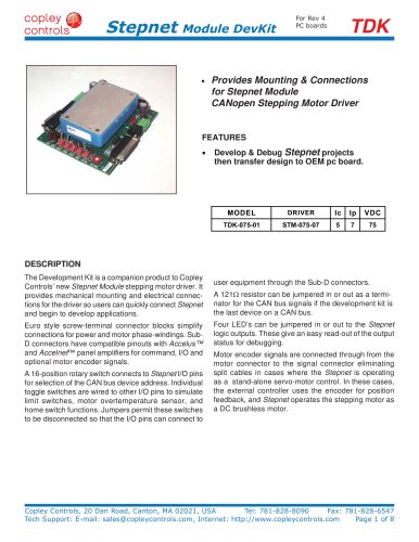
DESCRIPTION
Accelnet R20 is a ruggedized high-performance, DC powered drive for position, velocity (using encoder, resolver, Halls, or BEMF), and
torque control of brushless and brush motors. It operates as a distributed drive using the CANopen protocol, or as a stand-alone drive
accepting analog or digital commands from an external motion controller. In stand-alone mode, current and velocity modes accept
digital 50% PWM or PWM/polarity inputs as well as ±10V analog. In position mode inputs can be incremental position commands from
step-motor controllers, analog ±10V, or A/B quadrature commands from a master-encoder. Pulse to position ratio is programmable for
electronic gearing.
Accelnet R20 models operate as Motion Control Devices under the DSP-402 protocol of the CANopen DS-301 V4.01 (EN 50325-4)
application layer. DSP-402 modes supported include: Profile Position, Profile Velocity, Profile Torque, Interpolated Position Mode (PVT),
and Homing. The two CAN ports are optically isolated from drive circuits.
There are twelve digital inputs eleven of which have programmable functions. These include CAN address, motion-abort, limit & home
switches, stepper/encoder pulse inputs, reset, digital torque or velocity reference, and motor over-temperature. Input [IN1] is dedicated
for the drive Enable. There are three programmable logic outputs for reporting an drive fault, motor brake control, or other status
indications.
Drive power is transformer-isolated DC from regulated or unregulated power supplies. An AuxHV input powers control circuits for “keepalive” operation permitting the drive power stage to be completely powered down without losing position information, or communications
with the control system.
RUGGEDIZED STANDARDS CONFORMANCE
Ambient Temperature
Thermal Shock
Relative Humidity
Vibration
Altitude
Shock
MIL-STD specifications
IEC specifications
Non-Operating
Operating
Operating
Non-Operating
Operating
Operating
Non-Operating
Operating
Crash Safety
Operating
MIL-STDIEC-
-50ºC to 85ºC
-40ºC to 70ºC
-40ºC to 70ºC in 1 minute
95% non-condensing at 60ºC
95% non-condensing at 60ºC
5 Hz to 500 Hz, up to 3.85 grms
-400 m to 12,200 m
-400 m to 5,000 m
75 g peak acceleration
40 g peak acceleration
461, 704, 810, 1275, 1399
60068, 60079
Copley Controls, 20 Dan Road, Canton, MA 02021, USA
Tel: 781-828-8090
Tech Support: E-mail: sales@copleycontrols.com, Internet: http://www.copleycontrols.com
Fax: 781-828-6547
Page 1 of 24