عضویت
عضویت  ورود اعضا
 راهنمای خرید


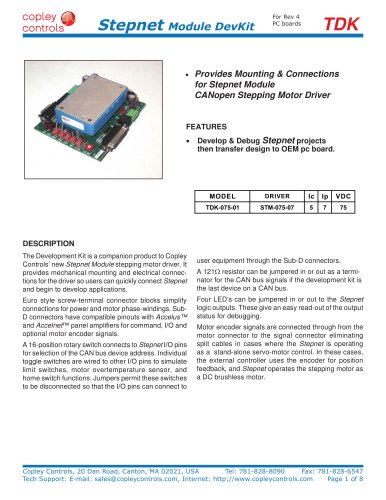
Accelnet R230 pages

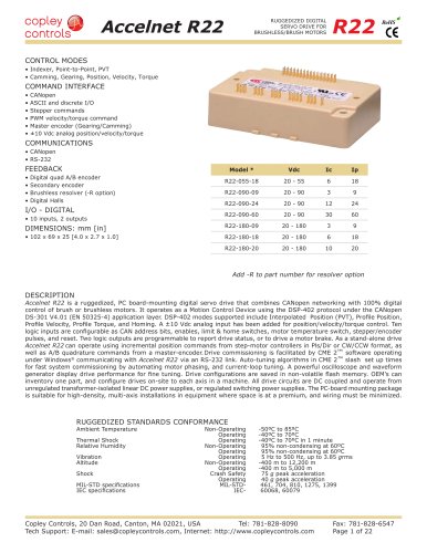
Accelnet R23
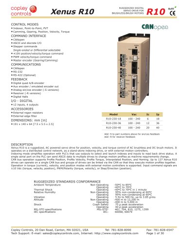
RUGGEDIZED DIGITAL
SERVO DRIVE FOR
BRUSHLESS/BRUSH MOTORS
R23
RoHS
CONTROL MODES
•tIndexer, Point-to-Point, PVT
•tCamming,tGearing,tPosition,tVelocity,tTorque
COMMAND INTERFACE
•tCANopen
•tASCIItandtdiscretetI/O
•tSteppertcommands
•t±10Vtposition/velocity/torquetcommand
•tPWMtvelocity/torquetcommand
•tMastertencodert(Gearing/Camming)
COMMUNICATIONS
•tCANopen
•tRS232
Model
FEEDBACK
Ic
Ip
Vdc
14~55
•tDigital Quad A/B encoder
•tSecondarytencoder
•tDigitaltHalls
•tResolvert(-Rtoption)
R23-055-06
3
6
R23-055-10
5
10
20~55
R23-090-04
2
4
14~90
I/O - DIGITAL
R23-090-08
4
8
20~90
•t10tinputs,t3toutputs
FOR RESOLVER OPTION, ADD “-R” TO THE PART NUMBER
DIMENSIONS: mm [in]
•t64 x 41 x 16 [2.5 x 1.6 x 0.6]
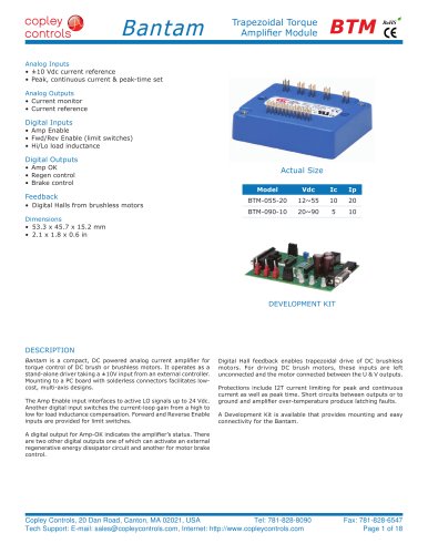
DESCRIPTION
Accelnet R23 is a digital servodrive that combines CANopen networking
with 100% digital control of brush or brushless motors in a pc board
mounting package.
Accelnet R23 operates as a Motion Control Device using the DSP-402
protocol under the CANopen DS-301 V4.01 (EN 50325-4) application
layer. DSP-402 modes supported include Interpolated Position (PVT),
Profile Position, Profile Velocity, Profile Torque, and Homing.
There are ten logic inputs. One is dedicated to the Amp Enable function,
the other nine are programmable. There are three logic outputs rated
to +30 Vdc.
Used as a stand-alone drive, Accelnet R23 can operate using incremental
position commands from step-motor controllers in Pulse/Direction or
CU/CD format, as well as A/B quadrature commands from a masterencoder. Torque or velocity control can be from digital PWM signals, or
analog ±10 V.
Drive commissioning is facilitated by CME 2™ software operating under
Windows® communicating with Accelnet R23 via CAN or an RS-232
link.
Auto-tuning algorithms in CME 2™ slash set up times for fast system
commissioning by automating motor phasing, and current-loop tuning.
A powerful oscilloscope and waveform generator displays drive
performance for fine tuning. Drive configurations are saved in non-volatile
flash memory. OEM’s can inventory one part, and configure drives onsite to each axis in a machine.
Space-vector modulation delivers higher motor speeds and lower motor
power dissipation than conventional sine-pwm modulation. Carriercancellation modulation all but eliminates motor ripple current and
dissipation at a standstill. Current-loop sampling is at 15 kHz, position
and velocity loops at 3 kHz and PWM ripple at 30 kHz.
All drive circuits are DC coupled and operate from unregulated
transformer-isolated linear DC power supplies, or regulated switching
power supplies.
The pc-board mounting package is suitable for high-density, multi-axis
installations in equipment where space is at a premium, and wiring must
be minimized.
RUGGEDIZED STANDARDS CONFORMANCE
Ambient Temperature
Thermal Shock
RelativetHumidityt
Vibrationt
Altitude
Shock
MIL-STDtspecificationst
IECtspecificationst
Non-Operating
Operating
Operating
Non-Operatingt
Operatingt
Operatingt
Non-Operating
Operating
Crash Safety
Operating
MIL-STD-t
IEC-t
-50ºC to 85ºC
-40ºC to 70ºC
-40ºC to 70ºC in 1 minute
t 95%tnon-condensingtatt60ºC
t 95%tnon-condensingtatt60ºC
t 5tHzttot500tHz,tupttot3.85tgrms
-400 m to 12,200 m
-400 m to 5,000 m
75 g peak acceleration
40 g peak acceleration
t461,t704,t810,t1275,t1399
t60068,t60079
Copley Controls, 20 Dan Road, Canton, MA 02021, USA
Tel: 781-828-8090
Tech Support: E-mail: sales@copleycontrols.com, Internet: http://www.copleycontrols.com
Fax: 781-828-6547
Page 1 of 24