عضویت
عضویت  ورود اعضا
 راهنمای خرید

0240400 pages

Issue 02-13*
240-40
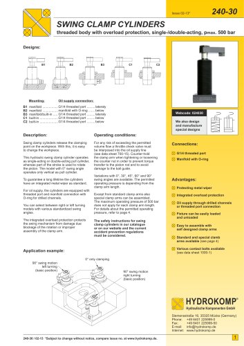
SWING CLAMP CYLINDERS
block housing with overload protection, single-/double-acting, pmax. 500 bar
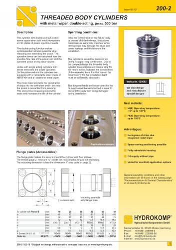
Description:
Operating conditions:
Swing clamp cylinders release the clamping
point on the workpiece. With this, it is easy
to change the workpiece.
For any risk of exceeding the permitted
volume flow a throttle check valve must
be interposed into the oil supply line
(see data sheet 700-15).
This hydraulic swing clamp cylinder operates
as double-acting pull cylinder, whereas part
of the stroke is used to rotate the piston.
The model with 0° swing angle operates
only vertical as pull cylinder.
To guarantee a long lifetime the cylinders
have an integrated metal wiper as standard.
For hydraulic oil supply, the cylinders are
equipped with threaded port and manifold
connection with O-ring for drilled channels.
Counter-hold the clamp arm when tightening
or loosening the counter nut in order to
prevent torque transfer to the piston rod
and to avoid damage to the ball guide.
Models with 0°, 30°, 45°, 60° and 90° swing
angles are available. The permitted operating
pressure is depending from the clamp arm
length. Models with other swing angles can
be supplied as special designs
Except from standard clamp arms also
special clamp arms can be assembled.
The maximum operating pressure of 500 bar
does not apply for each clamp arm length.
For details about the permitted operating
pressure see the diagrams below.
You can select between right or left turning
models with various standardized swing
angles.
The safety instructions for swing
clamp cylinders in our catalogue
or on our website and the current
accident prevention regulations
must be considered.
The integrated overload protection protects
the swing mechanism from demage due
blockage of the rotation or improper
assembly of the clamp arm.
Webcode: 024040
We also design
and manufacture
special designs
Connections:
G1/4 threaded port
Manifold with O-ring
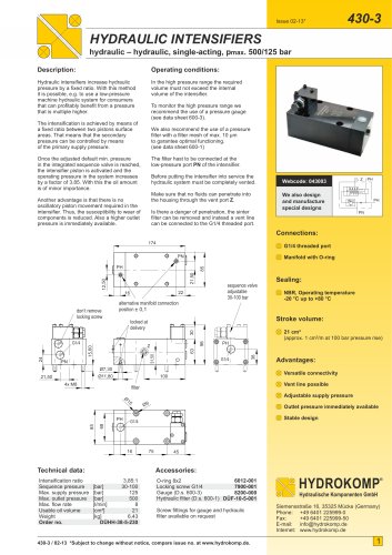
Effective clamping force FSp depending from operating pressure p:
e
e e
e e
Advantages:
Protecting metal wiper
Integrated overload protection
FSp
FSp
FSp
FSp
Oil supply through drilled channels
or threaded port connection
Piston Ø 25 mm
Piston Ø 40 mm
Piston Ø 63 mm
Fixture can be easily
loaded and unloaded
Effective clamping force FSp [kN]
9
18
8
16
7
6
4
10
45
40
35
14
12
5
24
0
16
0
12
0
96
80
68
60
53
48
15
0
10
0
75
60
50
43
38
34
10
0
66
50
40
33
29
25
Maximum clamp arm length e [mm], only relevant for clamp arms type
Example B
30
Easy to assemble with
self designed clamp arms
Standard and special clamp
arms available (see page 2)
25
8
6
15
2
4
10
1
2
Various contact bolts available
(see data sheet 1000-1)
20
5
3
Example A
0
0 100 200 300 400 500
0
0 100 200 300 400 500
0
0 100 200 300 400 500
Operating pressure p [bar]
HYDROKOMP
®
Example A:
- cylinder with piston Ø 25 mm
- present operating pressure p = 250 bar
- clamp arm type 2, length 40 mm
resulting clamping force FSp ~ 2,5 kN
Example B:
- cylinder with piston Ø 40 mm
- present operating pressure p = 250 bar
- clamp arm type 1, length e = 60 mm
resulting clamping force FSp ~ 8,5 kN
240-40 / 02-13 *Subject to change without notice, compare issue no. at www.hydrokomp.de.
Hydraulische Komponenten GmbH
Siemensstraße 16, 35325 Mücke (Germany)
Phone: +49 6401 225999-0
Fax:
+49 6401 225999-50
E-mail: info@hydrokomp.de
Internet: www.hydrokomp.de
1
"