عضویت
عضویت  ورود اعضا
 راهنمای خرید

070030E0 pages

Issue 02-13*
700-30
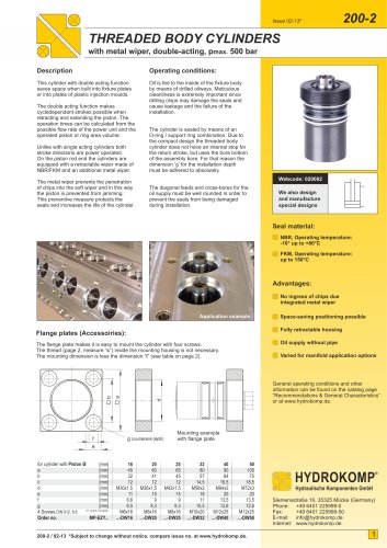
PRESSURE REDUCING VALVES
without leak-oil connection, pmax. 500 bar
General information:
Important information:
Pressure reducing valves are ideal for the
application in static leak-oil free clamping
systems, which are decoupled by a pressure
pump unit.
Since this pressure reducing valve does not
have a leak-oil port, an supply pressure rise
might not be compensated.
The function of the pressure reducing valve
is to maintain the outlet pressure A on the
consumer also with variable, always higher
supply pressure P constant.
Reasons for such an unwanted pressure
rise can be for example: warming, external
influences, effects by foreign matter (chips)
in the valve seat etc.
Overload balance is not possible due to
this pressure reducing valve version.
Function:
Once the supply pressure equals the
adjusted outlet pressure, a check valve
completely blocks the oil flow. Therefore,
the pressure can not increase any more.
Until the adjusted outlet pressure is acquired,
the hydraulic oil can easily flow from P→A
through the valve.
A pressure spring opens the oil flow against
the supply pressure, as soon as the outlet
pressure, e.g. due to the consumer,
decreases. This makes the hydraulic oil flow
until the initial pressure is acquired again.
HYDROKOMP recommends installing
a pressure reducing valve between the
valve and the consumer.
The opening pressure adjusted for the
pressure reducing valve may not exceed the
max. permissible operating pressure of the
consumer. If possible, it should be approx.
10% above the outlet pressure.
Webcode: 070030
A
Other designs
are available
on request
P
The outlet pressure can be adjusted by
a pressure gauge which also allows the
visual control of the outlet pressure.
Advantages:
Optimal use of clamping force with
cylinders and cylinder groups
Automatic adjustment for
outlet pressure
Ideal for static clamp systems
No leak-oil tubes
Housing with pressure gauge port
Varied settings possible
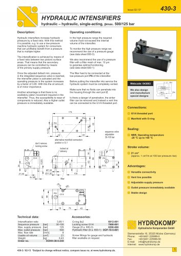
Installation screw-in valve:
For illustration see page 2
1. Turn back the counter- and sealing nut
right to the end position.
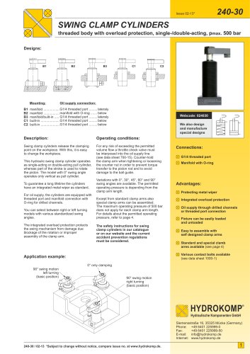
Screw-in valve
Pipe connection
Manifold connection
Application example:
2. Now screw in the valve housing and
fasten it with 70 Nm.
(metal sealing to 118° counter bore)
3. Fasten the counter- and sealing nut
with 60 Nm. The sealing is made with
support of the enclosed edge seal on
the 30-mm countersink diameter.
4. For dismantling please proceed in the
opposite order.
HYDROKOMP
®
Hydraulische Komponenten GmbH
If throttle check valves and sequence valves are to be combined in sequence with the
pressure reducing valve, the order described in the example must be considered.
700-30 / 02-13 *Subject to change without notice, compare issue no. at www.hydrokomp.de.
Siemensstraße 16, 35325 Mücke (Germany)
Phone: +49 6401 225999-0
Fax:
+49 6401 225999-50
E-mail: info@hydrokomp.de
Internet: www.hydrokomp.de
1
"