عضویت
عضویت  ورود اعضا
 راهنمای خرید

043004E0 pages

430-4
Issue 02-13*
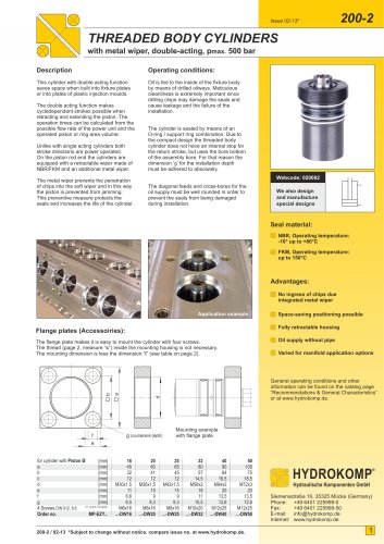
HYDRAULIC INTENSIFIERS
pneumatic – hydraulic, single-acting/double-acting
Description:
Functionality:
This hydraulic intensifier transmits the energy
from a pneumatic system connected ahead
onto the hydraulic system.
Once compressed air is supplied a piston
with high-pressure pipe is pushed against a
plunger. After a short length of stroke a nonreturn element with sealing separates the
high pressure chamber from the reserve
chamber.
The transmission is loss-free in a set ratio
without interfering oscillations. Electrical
signal processing systems control the
sequence in the pneumatic part. Due to the
high flow speed the converted energy is
quickly provided to the hydraulic consumers.
With the aid of the hydraulic intensifier,
hydraulic consumers that require higher
pressure can be actuated by a lower
pneumatic ingoing pressure that way.
The area ratio of piston and plunger affect
the increase in pressure in the hydraulic
intensifier. The increase of pressure during
the stroke is depending on the force that the
pressure inlet. The back stroke is made
trough de-aeration of the compressed air
part.
Single-acting
Operating condition:
Before operation the hydraulic intensifier is
to be filled with hydraulic oil and must be deaerated in the hydraulic system.
In order to check the oil level, the hydraulic
intensifiers are equipped with an oil level
window as standard.
An electrical oil level control is available as
accessory part (see page 2). This electrical
control automatically detects a minus and
with that makes oil level control in the
hydraulic part easier.
The oil volume of the driving cylinder is
pushed backwards until the non-return
element opens. Compensation of the
pressurizing medium is made automatically.
For that, the piston is pulled by a magnet
into its end position (up to pneumatic-piston
Ø up to 140 mm).
Webcode: 043004
Other designs
are available
on request
H1
P1
P2
P3
Connections:
There is no oil loss by leakage. Secured by
non-return element and sealing losses are
always directed into a reserve chamber.
That makes the ingress of air impossible.
In order to shorten compensation time we
recommend to provide a constant feed
pressure to the hydraulic intensifier of
0.5 to 1 bar. For those types with pneumatic
piston Ø > 140 mm this is mandatory as
these to not have a magnetically controlled
back stroke.
G1/4, G3/8 or G1/2 threaded port
Operating medium:
Compressed air, filtered,
oiled or unoiled
Hydraulic oil, ISO VG 32, DIN 51 524
Operating pressure:
Double-acting
In order to increase driving power and speed,
the hydraulic intensifier can be operated
double-acting. In doing so, feed pressure
is to be 0.5 to 12 bar. With this procedure
it is prevented to cause under pressure in
pipes and driving cylinder. In addition a
quick aeration valve can be implemented.
Compressed air side 0.5 to 10 bar
Operating temperature:
15° C up to 80° C, with electrical
oil level control up to 60° C
Advantages:
Fast loss-free pressure transfer
No interfering oscillations
No underpressures in the system
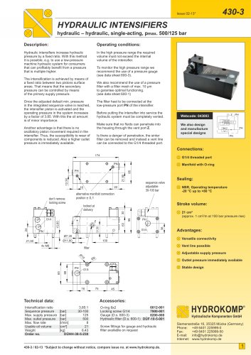
Application example:
Leakage-free operation with reserve
With oil level control
Hydropneumatic drive with
hydraulic intensifier
Hydropneumatic cylinder
Hydraulic intensifier
Throttle check valve
Check valve
Pneumatic directional valve
430-4 / 02-13 *Subject to change without notice, compare issue no. at www.hydrokomp.de.
Low-wear construction
HYDROKOMP
®
Hydraulische Komponenten GmbH
Siemensstraße 16, 35325 Mücke (Germany)
Phone: +49 6401 225999-0
Fax:
+49 6401 225999-50
E-mail: info@hydrokomp.de
Internet: www.hydrokomp.de
1
"