عضویت
عضویت  ورود اعضا
 راهنمای خرید

043003E0 pages
Issue 02-13*
430-3
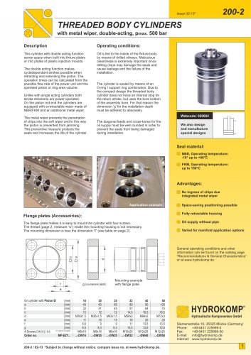
HYDRAULIC INTENSIFIERS
hydraulic – hydraulic, single-acting, pmax. 500/125 bar
Description:
Operating conditions:
Hydraulic intensifiers increase hydraulic
pressure by a fixed ratio. With this method
it is possible, e.g. to use a low-pressure
machine hydraulic system for consumers
that can profitably benefit from a pressure
that is multiple higher.
In the high pressure range the required
volume must not exceed the internal
volume of the intensifier.
To monitor the high pressure range we
recommend the use of a pressure gauge
(see data sheet 600-3).
The intensification is achieved by means of
a fixed ratio between two pistons surface
areas. That means that the secondary
pressure can be controlled by means
of the primary supply pressure.
We also recommend the use of a pressure
filter with a filter mesh of max. 10 µm
to garantee optimal functioning.
(see data sheet 600-1)
Once the adjusted default min. pressure
in the integrated sequence valve is reached,
the intensifier piston is activated and the
operating pressure in the system increases
by a factor of 3.85. With this the oil amount
is of minor importance.
The filter hast to be connected at the
low-pressure port PN of the intensifier.
Before putting the intensifier into service the
hydraulic system must be completely vented.
Make sure that no fluids can penetrate into
the housing through the vent port Z.
Another advantage is that there is no
oscillatory piston movement required in the
intensifier. Thus, the susceptibility to wear of
components is reduced. Also a higher outlet
pressure is immediately available.
Is there a danger of penetration, the sinter
filter can be removed and instead a vent line
can be connected to the G1/4 threaded port.
Webcode: 043003
Z
We also design
and manufacture
special designs
PH
PH
PN
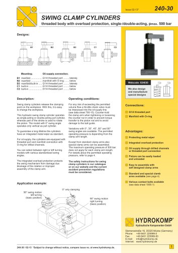
Connections:
174
G1/4 threaded port
PN
Manifold with O-ring
12,50
21,50
85
PH
22
16
don’t remove
locking screw
alternative manifold connection
position ± 0,1
30
Z
PH
PN
G1/4
38
31,50
63
15,60
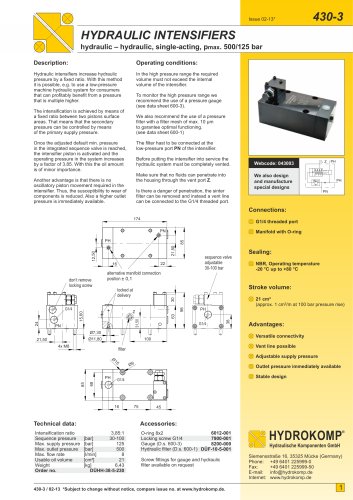
21 cm³
(approx. 1 cm³/m at 100 bar pressure rise)
98
G1/4
Ø7,30
4x M8
Vent line possible
filter
Adjustable supply pressure
Ø
15
68
85
PH
Ø9
Outlet pressure immediately available
Stable design
G1/4
16
Technical data:
Advantages:
Versatile connectivity
100
Ø11,80
21,50
Intensification ratio
Sequence pressure
Max. supply pressure
Max. outlet pressure
Max. flow rate
Usable oil volume
Weight
Order no.
NBR, Operating temperature
-20 °C up to +80 °C
Stroke volume:
locked at
delivery
24
Sealing:
sequence valve
adjustable
30-100 bar
75
45
Accessories:
3,85:1
[bar]
30-100
[bar]
125
[bar]
500
8
[l/min]
21
[cm³]
6,43
[kg]
DÜHH-38-5-230
6012-001
O-ring 8x2
Locking screw G1/4
7900-001
Gauge (D.s. 600-3)
8200-000
Hydraulic filter (D.s. 600-1) DÜF-10-5-001
Screw fittings for gauge and hydraulic
filter available on request
430-3 / 02-13 *Subject to change without notice, compare issue no. at www.hydrokomp.de.
HYDROKOMP
®
Hydraulische Komponenten GmbH
Siemensstraße 16, 35325 Mücke (Germany)
Phone: +49 6401 225999-0
Fax:
+49 6401 225999-50
E-mail: info@hydrokomp.de
Internet: www.hydrokomp.de
1
"