عضویت
عضویت  ورود اعضا
 راهنمای خرید


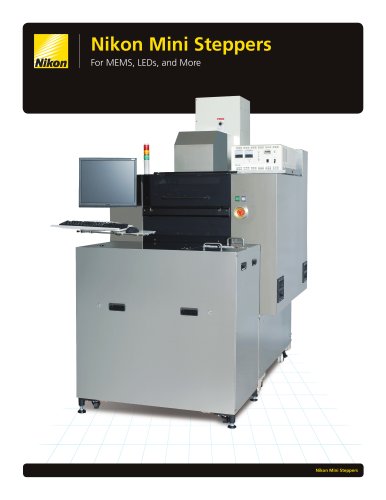
Compact Microscopes CM series0 pages
Microscope Components
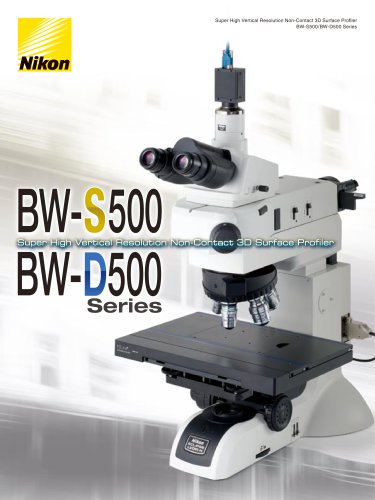
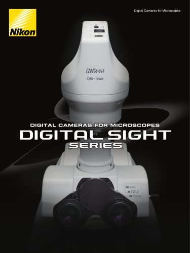
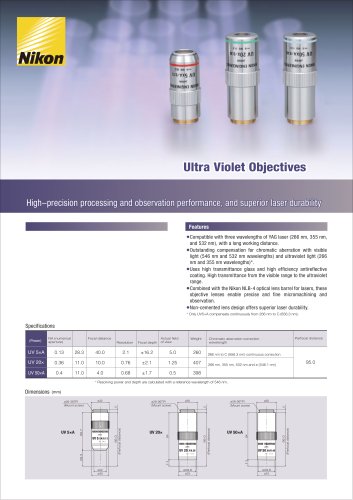
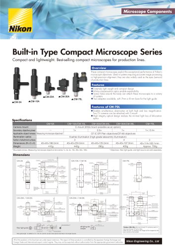
Built-in Type Compact Microscope Series
Compact and lightweight. Best-selling compact microscopes for production lines.
Overview
These compact microscopes exploit the exceptional performance of Nikon’s
microscope objectives. Used in systems requiring accurate image processing
or high-precision alignment, they are also widely used as the eyes (sensors)
of production lines.
Features
and
design
•Extremely light weightopticscompact expansibility
enable
•Infinity-compensationthe body can attach these microscopes to a variety
Screw holes
•of systems around
•Two adapters available, with 7mm or 8 mm bore for the light guide
Features of CM-70L
Enables simultaneous observation at
•Two TV cameras can be attached withboth high and low magnification.
C-mount
High
•opticsintegrity optical design realizes the minimal light loss of bifurcation
Specifications
CM 5A
Camera mount
Secondary objective power
Applicable object lenses Measuring microscope objectives*
Illumination optics
Number of attachment surfaces
Dimensions (W x D x H)
40×40×186.5mm
Weight
410g
CM 10A/CM-10L
CM 20A/CM-20L
CM 30A/CM-30L
C-mount (ENG mount possible as an option)
1×
0.5×
1×
CF IC EPI Plan objectives/CFI 60 objectives
Koehler illumination (high-grade telecentric illumination)
3
4
40×40×224.5mm
40×40×125.5mm
40×40×107.3mm
440g
290g
400g
CM 70L
1× / 0.4×
3
40×114×163.1mm
Approx. 700g
* Objectives, fiber light guide, and light source are sold separately.
* Mountable lenses: Measuring microscope objective lens series 1x, 3x, 5x, 10x, 20x, 50x, 100x
CM 10A / CM-10L
Mounting surface of C-mount
ø21
Mounting surface
of objective lens
42.3
Object
surface
ø 20
Fiber light guide
3
Transmission end
CM side
34
ø8
Fiber bundle diameter : ø5
ø 15
3
26.3
ø8 light guide
adapter
ø23
30
ø27
42.3
5
Mounting
surface of
objective lens
ø7(ø8)
Hole for attaching light guide
Light guide adapter
(interchangeable)
(Same as with the CM-10.)
Object
surface
Hole for attaching light guide
ø 21
10
25
ø 10
(10)
ø7
10
Screw for securing
light guide adapter
Screw for securing
light guide adapter
156.1
Light guide adapter
(interchangeable)
(Same as with the CM-10.)
25
(15)
17.526
CM-10A:45
CM-10L:60
ø7(ø8)
Hole for attaching light guide
60
22
40
74
102.2
(Hole for attachment screw)
(Same position on opposite side
2-M3
1-M3
40
4-M4 depth 5
(Hole for attachment screw)
(Same position on
opposite side)
22
8-M4 depth 5
30
2-M3
Screw for securing
light guide adapter
1-M3
Screw for securing light guide
40
40
103.3
16
ø23
ø27
30
30
(Hole for attachment screw)
(Same position on opposite side
6
Mounting surface
of C-mount
20
Mounting surface
of C-mount
8-M4 depth 5
53
ø7(ø8)
Hole for attaching light guide
53
1-M3
Screw for securing light guide
Imaging
plane
×
ø37
17.526
Imaging
plane
C-mount
1-M3
Screw for securing
C-mount
73
0.4×
C-mount
CM-30A:45
CM-30L:60
Object
surface
40
ø7
Hole for attaching light guide
ø38
72
CM-20A:45
CM-20L:60
Mounting surface
of objective lens
4-M4 depth 5
(Hole for attachment screw)
30
22
126
121.5
30
5
15
1-M3
Screw for securing light guide
ø27
30
ø23
5
(Hole for attachment
screw
2-M3
Screw for securing
light guide adapter
W.D.
2-M3
Screw for securing
light guide adapter)
ø27
ø23
5
220.5
40
8-M4 depth 5
30
22
20 40
15
40
42.3
40
4-M4 depth 5
5
ø31
Mounting surface
of C-mount
ø37
(Hole for attachment
screw
42.3
CM 30A / CM-30L
ø38
30
interchangeable
Mounting surface
of objective lens
17.526
Imaging plane
C-mount
ø8
Hole for attaching light guide
26.3
Object
surface
CM 20A / CM-20L
5
Light guide adapter
40
8-M4 depth 5
40
ø28
34
ø23
50
71
66
Object
surface
8-M4 depth 5
ø37
(Hole for attachment screw)
(Same position on opposite side
Light guide adapter
(interchangeable)
(Same as with the CM-10.)
Measuring
microscope
Objective
lens
(Hole for attachment screw)
(Same position on opposite side
1-M3
Screw for securing
light guide
ø7(ø8)
Hole for attaching
light guide
30
Mounting surface
of objective lens
2-M3
Screw for securing
C-mount
2-M3
Screw for securing
C-mount
70
89.2
182.5
40
40
40
5
3-M3
Screw for securing
C-mount
ø38
2-M3
Screw for securing
light guide adapter)
(Hole for attachment screw)
(Same position on opposite side
65
ø37
30
CM 70L
Mounting surface
of C-mount
8-M4 depth 5
4-M4 depth 5
(Hole for
attachment screw
5
Imaging plane
C-mount
ø38
2-M3
Screw for securing
C-mount
17.526
Imaging plane
C-mount
CM 5A
17.526
Dimensions
Set screw clearance
Notes (CM-70L) We recommend TV cameras used on
the 0.4x end be 1/2 inch or less.
With 2/3 inch TV cameras, the image will be cropped at the
four corners of the screen.
Fiber guide length : In addition to 1m, 1.5m, 2m, and 5m, we also make special order fibers in the length required.
All of the products in this brochure are under export restriction. The export of these products is controlled by the Japanese Foreign Exchange and
Foreign Trade and International export control regime. They may not be exported without authorization from the appropriate government authorities.
Nikon Engineering Co., Ltd
"