عضویت
عضویت  ورود اعضا
 راهنمای خرید


CB123ALC0 pages

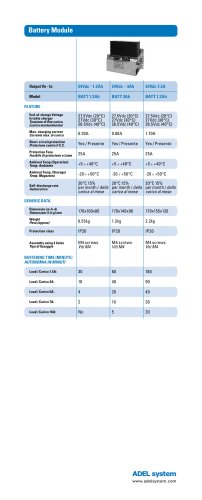
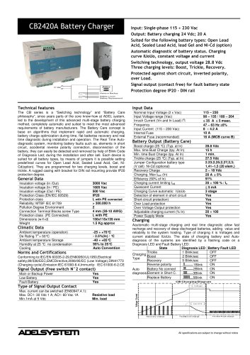
CB123A/LC Battery Charger
Technical features
Input Data
The CB series is a “Switching technology” and “Battery Care
philosophy”, since years parts of the core know-how at ADEL system,
led to the development of this advanced multi-stage battery charging
method, completely automatic and suited to meet the most advanced
requirements of battery manufacturers. The Battery Care concept is
base on algorithms that implement rapid and automatic charging,
battery charge optimization during time, flat batteries recovery and real
time diagnostic during installation and operation. The Real Time Autodiagnostic system, monitoring battery faults such as, elements in short
circuit, accidental reverse polarity connection, disconnection of the
battery, they can easily be detected and removed by help of Blink Code
of Diagnosis Led; during the installation and after sell. Each device is
suited for all battery types, by means of jumpers it is possible setting
predefined curves for Open Lead Acid, Sealed Lead Acid, Gel, NiCd(option). They are programmed for two charging levels, boost and
trickle. A rugged casing with bracket for DIN rail mounting provide IP20
protection degree. They are extremely compact and cost-effective.
General Data
Insulation voltage (In /Out)
Insulation voltage (In / PE)
Insulation voltage (Out / PE)
Protection Class (EN/IEC 60529)
Protection class
Reliability: MTBF IEC 61709
Pollution Degree Environment
Connection Terminal Blocks screw Type
Dimensions (w-h-d)
Weight
3000 Vac
1605 Vac
500 Vac
IP20
I, with PE connected
> 300.000 h
2
2,5mm(24–14AWG)
45x100x100 mm
0.30 Kg approx
Ambient temperature (operation)
De Rating Ta > 50°C
Ambient temperature Storage
Humidity at 25 °C no condensation
Cooling
-25 ÷ +70°C
- 2.5%(In) / °C
-40 ÷ +85°C
95% to 25°C
Auto Convention
Climatic Data
Norms and Certifications
Conforming to:IEC/EN 60335-2-29,EN60950/UL1950,Electrical
safety,89/336/EEC,EMCDirective,2006/95/EC (Low Voltage),DIN41773
(Charging cycle),Emission:IEC 61000-6-4,Immunity: IEC 61000-6-2.CE
Signal Output (free switch contact)
Model
Main or Backup Power
Low Battery
Fault Battery
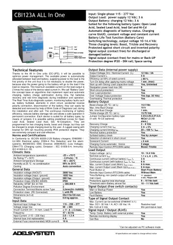
Input: Single-phase 115 230 Vac
Output: Battery charging 12 Vdc; 3 A
Suited for the following battery types: Open Lead
Acid, Sealed Lead Acid, lead Gel and Ni-Cd (option)
Automatic diagnostic of battery status. Charging
curve IUoUo, constant voltage and current
Switching technology, output voltage 14.4 Vdc
Three charging levels: Boost, Trickle, Recovery.
Protected against short circuit, inverted polarity,
over Load.
Signal output (contact free) for fault battery state
Protection degree IP20 - DIN rail
CB123A
Yes
Yes
Yes
CB123ALC
No
No
No
Nominal Input Voltage (2 x Vac)
Input Voltage range (Vac)
Inrush Current (Vn and In Load) I2t
Frequency
Input Current (115 – 230 Vac)
Internal Fuse
External Fuse (recommended)
115 – 230 – 277
90 – 305
11 A 5 msec.
47 – 63 Hz 6%
0.5 – 0.3 A
4A
10 A (MCB curve B)
Battery Output (Battery Care)
Model
Adjustable charging current Iadj (% In)
Boost charge (25 °C) (typ. at In)
Max. time Bust Charge (tpy. at In)
Min. time Bust Charge (tpy. at In)
Trickle charge (25 °C) (typ. at In)
Jumper Configuration battery type
(V cell) Ni-Cd (optional)
Recovery Charge
Charging. Max Ibatt (In)
Efficiency (50% - In)
Quiescent Current
Charging Curve automatic: IUoUo
Detection of element in short circuit
Short-circuit protection)
Over Load protection
Over Voltage Output protection
CB123A
CB123ALC
20 ÷ 100
No
14.4 Vdc
15 h
70 min.
13.75 Vdc
2.23;2,25;2,27;2,3;
1,41–1,5 (20 elem.)
2 – 7 Vdc
3 A 5%
81%
5 mA
3 stage
Yes
Yes
Yes
Yes
Charging
Aautomatic multi-stage charging and real time diagnostic allow fast
recharge and recovery of deep discharged batteries, adding value and
reliability to the system hosting. Type of charging it is Voltages and
current stabilized IUoUo. The state of charging battery and Autodiagnosis of the systems are identified by a flashing code on a
Diagnosis LED and Fault Battery LED:
State
Diagnosis LED Battery Fault LED
Trickle
1 Blink/sec
OFF
Charging
Boost
2 Blink/sec
OFF
Type
Recovery
5 Blink/sec
OFF
Reverse polarity
ON
1Blink
Battery No connect
2Blink
ON
Auto
ON
diagnosis Element in Short C.
3Blink
Replace Battery
ON
5Blink
Type of Signal Output Contact
Max. current can be switched (EN60947.4.1):
Max. DC1: 30 Vdc 1 A; AC1: 60 Vac 1A
Min.1mA at 5 Vdc
Resistive load
Min load
All specifications are subject to change without notice
"