عضویت
عضویت  ورود اعضا
 راهنمای خرید
LOADING

PRESSURE SWITCHES Catalogue DS-117 B M120 pages

نسخه متنی
"
"
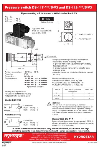
| Pipe mounting - G % female | ||||||||||||||||||||||||||||||||||||||||||||||||||
| IP 65 | ||||||||||||||||||||||||||||||||||||||||||||||||||
| Connection inlet M 12 x 1 | ||||||||||||||||||||||||||||||||||||||||||||||||||
| Weight: 0,27 kg | ||||||||||||||||||||||||||||||||||||||||||||||||||
| Pressure adjustment + locking by 2 screw tops with hexagonal recess 6 mm | ||||||||||||||||||||||||||||||||||||||||||||||||||
| C | ||||||||||||||||||||||||||||||||||||||||||||||||||
| switching point + switching point — | ||||||||||||||||||||||||||||||||||||||||||||||||||
| 30 | ||||||||||||||||||||||||||||||||||||||||||||||||||
| 41 | 0 5,3 | |||||||||||||||||||||||||||||||||||||||||||||||||
| Pressure adjustment - locking with one tool only. Locking of pressure adjustment as follows: By means ofa6mm wrench for socket head cap screws adjustment of switching point is done. Then with the same tool adjust the upper locking top in clockwise rotation. The pressure adjustment is now locked. | ||||||||||||||||||||||||||||||||||||||||||||||||||
| Oil connection | ||||||||||||||||||||||||||||||||||||||||||||||||||
| 6 mm hexagonal recess | ||||||||||||||||||||||||||||||||||||||||||||||||||
| Nominal switching capacity: Standard micro switch: Silver (Ag 999) CEE 24; VDE 0630 50 TSD circuits, T85 UL 1054/CSA C22.2 No. 55 6 TSD, T90 | ||||||||||||||||||||||||||||||||||||||||||||||||||
| Adjustable screw top for pressure adjustment | ||||||||||||||||||||||||||||||||||||||||||||||||||
| ||||||||||||||||||||||||||||||||||||||||||||||||||
| Ambient temperature: -40 °C up to + 90 °C | ||||||||||||||||||||||||||||||||||||||||||||||||||
| Protection: Connection: Pressure range: | IP 65 G 1A female 5- 70 bar 10-150 bar 20-240 bar 20-350 bar | |||||||||||||||||||||||||||||||||||||||||||||||||
| Pmax. = 200 bar Pmax. = 400 bar Pmax. = 500 bar P max. = 500 bar | ||||||||||||||||||||||||||||||||||||||||||||||||||
| A | ||||||||||||||||||||||||||||||||||||||||||||||||||
| NOTICE ! The unit must only be installed by an electrican. Comply with the national and international regulations for the installation of electro-technical equipment. Voltage supply in compliance with EN 50178, SELV, PELV. Ensure that the equipment is not energized before connecting the unit. Hysteresis DS-117/M12 | ||||||||||||||||||||||||||||||||||||||||||||||||||
| Working fluid: Hydraulic oil For use with Water brass housing Not possible for explosive gases Connection diagram DS-117/M12 | ||||||||||||||||||||||||||||||||||||||||||||||||||
| without pressure | ||||||||||||||||||||||||||||||||||||||||||||||||||
| For an adjustable pressure of approximately 60-70 % of max. adjustable pressure the Hysteresis is approximately 5-12 % of end value. | ||||||||||||||||||||||||||||||||||||||||||||||||||
| In order to retain service-life over a switching currents resp. inductive loads should | vibrations, oscillations and high as far as possible - be avoided. | |||||||||||||||||||||||||||||||||||||||||||||||||
| Dͤrmannsbusch 4, D-58456 Witten (Herbede) P. O. Box 31 65, D-58422 Witten (Herbede) Phone (0 23 02) 70 12-0, Fax (0 23 02) 70 12-47 Internet: www.hydropa.de - E-Mail: info@hydropa.de | ||||||||||||||||||||||||||||||||||||||||||||||||||
| HYDROSTAR | ||||||||||||||||||||||||||||||||||||||||||||||||||
| ■dmbii.iCeigci | ||||||||||||||||||||||||||||||||||||||||||||||||||
| hydropa 1.18/E 04/01 | ||||||||||||||||||||||||||||||||||||||||||||||||||
| 1.18/E-04.01-01 | ||||||||||||||||||||||||||||||||||||||||||||||||||
| Rights of alteration reserved in sense of technical development! | ||||||||||||||||||||||||||||||||||||||||||||||||||