عضویت
عضویت  ورود اعضا
 راهنمای خرید


RKB Guidelines for Mounting Four-Row Cylindrical Roller Bearings Poster0 pages

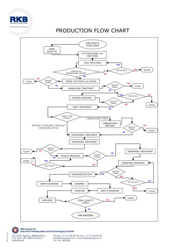
MOUNTING GUIDELINES FOR
nnnnRKB FOUR-ROW CYLINDRICAL ROLLER BEARINGS IN ROLLING MILL APPLICATIONS
nnnnBEARING INDUSTRIES
nnnn1 - Loose flange rings
nnnn2 - Outer rings
nnnn3 - Cages
nnnn4 - Rollers
nnnn5 - Central spacer
nnnn6 - Inner rings
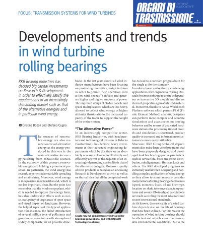
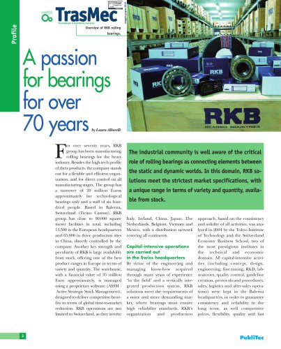
nnnnRKB multi-row cylindrical roller bearings are used almost exclusively to support the roll necks of back-
nnnnup rolls in rolling mill machinery. They are designed with well-balanced cross-sections to provide the
nnnnhighest possible radial load carrying capacity within the bearing envelope.
nnnnIn order to properly meet application requirements, RKB multi-row cylindrical roller bearings are
nnnnproduced in several designs and executions that basically differ in the number of inner and outer rings,
nnnnin the number of loose or integral flanges on the outer ring, in the cage type, in the number of rollers and
nnnnrelated arrangement in cage pocket.
nnnnMulti-row cylindrical roller bearings can accommodate only radial loads and tolerate moderate to high
nnnnmill speeds; possible axial loads have to be accommodated by other types of bearings (deep groove
nnnnball bearings, angular contact ball bearings, tapered roller bearings, tapered roller thrust bearings, or
nnnnspherical thrust roller bearings).
nnnnRKB four-row cylindrical roller bearings are of separable design, which considerably simplifies mounting,
nnnninspection and maintenance operations.
nnnnBoth inner rings (designation L) and outer ring assemblies (designation R) are interchangeable, this
nnnnbeing helpful for quick roll replacement.
nnnnOuter ring assemblies, consisting of outer rings, rollers, and cages, can be mounted independently of
nnnninner rings, or all bearing components can be mounted separately.
nnnnThe mounting of the bearing onto the roll neck has to be in accordance with the mounting instructions
nnnnsupplied with the rolling mill machinery design.
nnnnPRELIMINARY OPERATIONS
nnnn-
nnnn—L
nnnnPrior to mounting, measure the chock bore diameter in four equally spaced planes normal to the
nnnnbore axis of symmetry (a, b, c, d) and in each plane in four directions offset at 45° (1, 2, 3, 4). These
nnnnmeasurements have to be properly recorded.
nnnnMeasure the shaft diameter in four planes (or three, according to the neck shape) normal to the
nnnnshaft axis of symmetry (a, b, c, d) and in each plane in four directions offset at 45° (1, 2, 3, 4). These
nnnnmeasurements have to be properly recorded.
nnnnBore and shaft shape deviations are highly recommended to be measured as well. Record all these
nnnnmeasurements in a measuring report.
nnnnProperly lubricate bearing components according to the lubricant suggested in the rolling mill
nnnnmachinery design.
nnnnFor easy mounting, be sure that the chock and the shaft are clean and lubricated; this will reduce the
nnnnwear and corrosion of the assembly elements during operation.
nnnnMOUNTING OF INNER RINGS ONTO THE ROLL NECK
nnnnPush the labyrinth ring or backing ring (heated in an oil
nnnnbath) onto the roll neck until it abuts the roll body face
nnnnwithout a gap.
nnnnHeat the inner rings in an oil bath or, if available, using an
nnnninduction coil.
nnnnWhen the inner rings are heated in an oil bath, use a
nnnnthermostatto avoid excessively high heating temperature.
nnnnWipe off the oil in the bores and from the faces of the
nnnnbearing inner rings after they are removed from the oil
nnnnbath.
nnnnIf the roll neck end is not shaped to guide the inner
nnnnrings (stepped sections), we highly recommend using a
nnnnmounting sleeve.
nnnnIn case of small bearings, manually push the inner rings
nnnn(heated in an oil bath) on the roll neck.
nnnnIn case of large bearings, use mounting grippers, which
nnnnhave to carry the rings always with their axis in a horizontal
nnnnposition.
nnnnFor inner rings heated using an induction coil, push
nnnnSTEP I
nnnnmanually or using an appropriate lifting device the coil
nnnntogether with the bearing inner ring onto the roll neck.
nnnnWARNING!
nnnnAfter using an induction coil, bearing inner rings and
nnnnroll necks remain magnetized and have to be properly
nnnndemagnetized. This can be done by pulling the induction
nnnncoil itself over the mounted part with the current switched
nnnnon and slowly removing to a distance of 1-2 meters from the
nnnnparts.
nnnn• After cooling down, the rolling bearing inner rings should
nnnnabut the labyrinth ring without a gap.
nnnn• Inner rings of smaller bearings can be mounted without a
nnnngap between them by pushing a mounting sleeve against
nnnnthe ring face while the rings cool down.
nnnn• After mounting onto the roll neck,itis highly recommended
nnnnto measure the raceway diameters of the inner rings
nnnncarrying out the same procedure for measuring the shaft
nnnndiameter.
nnnnMOUNTING OF THE CHOCK ONTO THE ROLL NECK
nnnnSTEP
nnnnCheck if the labyrinth ring and the inner rings have been fitted onto the roll neck.
nnnnMount the seal neighboring the shaft shoulder onto the chock.
nnnnCarry in a horizontal position the pre-assembled chock (complete with outer ring assembly and bearings which should
nnnntake the axial loads) to the roll neck by means of a crane.
nnnnAlign the chock as closely as possible with the roll neck so that the chock can be easily pushed onto the roll neck.
nnnnCarefully push the pre-assembled chock onto the roll neck so that no score marks are produced on the rollers or inner
nnnnring raceways.
nnnnMount the axial clamping and the sealing system onto the shaft and make sure that it is properly adjusted and secured.
nnnnMOUNTING OF OUTER RINGS INTO THE CHOCK
nnnn1
nnnnSTEP
nnnnLARGE SIZE BEARINGS
nnnn• Fasten the roll-side cover onto the chock.
nnnn• Place the chock with its bore axis in horizontal
nnnnposition.
nnnn• Be sure that the outer rings have their axis aligned
nnnnwith the chock bore axis.
nnnn• Insert the rings into the chock using a beam
nnnnsuspended in ropes or cables.
nnnnSMALL AND MEDIUM SIZE BEARINGS
nnnnFasten the roll-side cover onto the chock.
nnnnPlace the chock on level supports with bore axis in
nnnnvertical position.
nnnnIn case of small bearings, manually insert the outer
nnnnrings into the chock.
nnnnIn case of medium bearings, insert the outer rings
nnnninto the chock by means of a special clamping/
nnnnlifting device or, when the bearing is provided with
nnnnthreaded holes for eye bolts, by means of ropes,
nnnncables or chains attached to the crane hook.
nnnnOn initial mounting, place the outer ring marked zone in the load direction and mark the position on the top
nnnnof the chock.
nnnnCarefully place the desired load zones of the outer rings in the same direction.
nnnnMake sure that adjacent parts abut each other completely and check the seating of the outer ring against
nnnnthe cover shoulder or loose flange with a feeler gauge.
nnnnIf need be, mount the bearing which should take the axial loads.
nnnnDISMOUNTING
nnnnDismounting of RKB four-row cylindrical roller bearings from the roll neck encompasses two distinct phases:
nnnn1) Withdrawal of the chock from the inner rings
nnnn• Remove the axial clamping and the sealing system from the roll neck.
nnnn• Carefully remove the chock from the roll neck as a complete unit.
nnnn• When only the rolls are replaced, mount the chock onto the new roll neck only after the inner rings have been
nnnninstalled on it.
nnnn• Dismount bearing components for inspection in the reverse order of mounting and using the same equipment.
nnnn2) Extraction of the inner rings from the roll neck
nnnn• If the inner rings are mounted with tight fit on the roll neck, use the same induction coil as for mounting.
nnnn• Quickly heat the inner rings in order to release the tight fit.
nnnnRKB GX DESIGN
nnnnThe RKB new generation four-row cylindrical roller bearings GX type introduce optimized features such as
nnnnthe double window-type cage, the alternate long/short roller arrangement and the inner ring with higher
nnnnchamfer on the raceway.
nnnnTo improve bearing lubrication there are annular grooves and lubrication holes on the outer rings and
nnnnlubrication grooves in their side faces.
nnnnThe special GX type configuration alternating long and short rollers has been introduced to get a better load
nnnndistribution and reduce the edge contact pressure typical of standard designs.
nnnnAnother important feature introduced by the RKB GX configuration is the higher chamfer angle and length on
nnnnthe inner ring raceway, specific for each different geometry.
nnnnThe controlled drop of rollers, obtained through the double window-type cage and the new dimension of the
nnnninner ring chamfer, permits a quicker and more efficient mounting with a much lower incidence of bearing
nnnndamages.
nnnnStandard design:
nnnnnot controlled drop of rollers
nnnnRKB GX design:
nnnncontrolled drop of rollers
nnnnWWW.RKBBEARINGS.COM
nnnnEngineered in Switzerland
nnnnTechnological Bearings
"