عضویت
عضویت  ورود اعضا
 راهنمای خرید


BEVEL GEARING0 pages
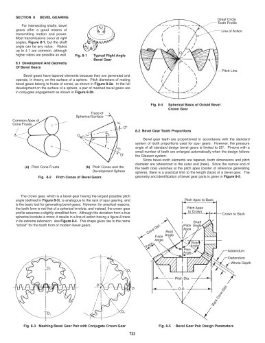
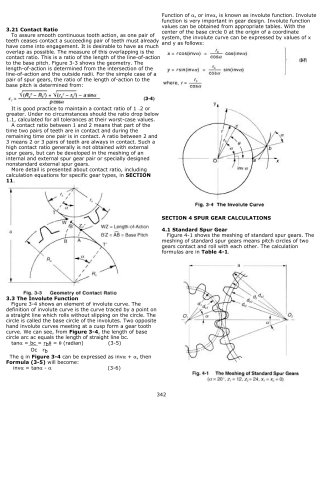
Fig. 8-1 Typical Right Angle Bevel Gear SECTION 8 BEVEL GEARING For intersecting shafts, bevel gears offer a good means of transmitting motion and power. Most transmissions occur at right angles, Figure 8-1 , but the shaft angle can be any value. Ratios up to 4:1 are common, although higher ratios are possible as well. 8.1 Development And Geometry Of Bevel Gears OP
Great Circle Tooth ProfileLine of Action
Pitch Line Bevel gears have tapered elements because they are generated and operate, in theory, on the surface of a sphere. Pitch diameters of mating bevel gears belong to frusta of cones, as shown in Figure 8-2a . In the full development on the surface of a sphere, a pair of meshed bevel gears are in conjugate engagement as shown in Figure 8-2b . The crown gear, which is a bevel gear having the largest possible pitch angle (defined in Fig. 8-4 Spherical Basis of Octoid Bevel Crown Gear Figure 8-5 . Common Apex of Cone FrustaTrace of Spherical Surface W >
2 8.2 Bevel Gear Tooth Proportions OO"O'P' G >
2 G Bevel gear teeth are proportioned in accordance with the standard system of tooth proportions used for spur gears. However, the pressure angle of all standard design bevel gears is limited to 20. Pinions with a small number of teeth are enlarged automatically when the design follows the Gleason system.
Since bevel-tooth elements are tapered, tooth dimensions and pitch diameter are referenced to the outer end (heel). Since the narrow end of the teeth (toe) vanishes at the pitch apex (center of reference generating sphere), there is a practical limit to the length (face) of a bevel gear. The geometry and identification of bevel gear parts is given in >
1 W >
1 Pitch Cone Frusta (b) Pitch Cones and the Development Sphere Figure 8-4 . This shape gives rise to the name "octoid" for the tooth form of modern bevel gears. Fig. 8-2 Pitch Cones of Bevel Gears(a) Figure 8-3 ), is analogous to the rack of spur gearing, and is the basic tool for generating bevel gears. However, for practical reasons, the tooth form is not that of a spherical involute, and instead, the crown gear profile assumes a slightly simplified form. Although the deviation from a true spherical involute is minor, it results in a line-of-action having a figure-8 trace in its extreme extension; see >
Cone Dist.Face Pitch AnglePitch Angle AddendumDedendumWhole Depth
Pitch Apex to BackPitch Apex to CrownCrown to BackPitch ApexShaft Angle
Pitch Dia. O.D.
Root AngleFace Angle Fig. 8-3 Meshing Bevel Gear Pair with Conjugate Crown Gear O >
2 2 PO PO >
Back Cone Dist. O >
1 1 O Fig. 8-5 Bevel Gear Pair Design Parameters >