عضویت
عضویت  ورود اعضا
 راهنمای خرید


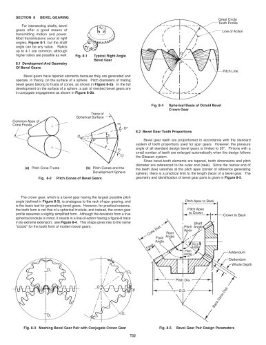
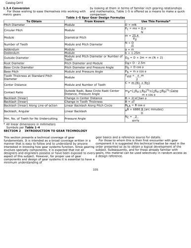
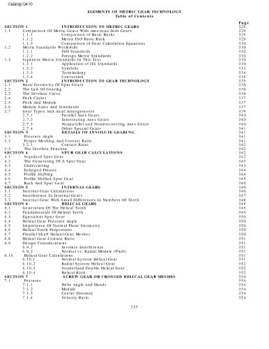
SPUR GEAR CALCULATIONS0 pages
3.21 Contact Ratio
To assure smooth continuous tooth action, as one pair of
teeth ceases contact a succeeding pair of teeth must already
have come into engagement. It is desirable to have as much
overlap as possible. The measure of this overlapping is the
contact ratio. This is a ratio of the length of the line-of-action
to the base pitch. Figure 3-3 shows the geometry. The
length-of-action is determined from the intersection of the
line-of-action and the outside radii. For the simple case of a
pair of spur gears, the ratio of the length of-action to the
base pitch is determined from:
It is good practice to maintain a contact ratio of 1 .2 or
greater. Under no circumstances should the ratio drop below
1.1, calculated for all tolerances at their worst-case values.
A contact ratio between 1 and 2 means that part of the
time two pairs of teeth are in contact and during the
remaining time one pair is in contact. A ratio between 2 and
3 means 2 or 3 pairs of teeth are always in contact. Such a
high contact ratio generally is not obtained with external
spur gears, but can be developed in the meshing of an
internal and external spur gear pair or specially designed
nonstandard external spur gears.
More detail is presented about contact ratio, including
calculation equations for specific gear types, in SECTION
11.
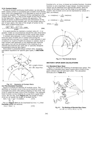
3.3 The Involute Function
Figure 3-4 shows an element of involute curve. The
definition of involute curve is the curve traced by a point on
a straight line which rolls without slipping on the circle. The
circle is called the base circle of the involutes. Two opposite
hand involute curves meeting at a cusp form a gear tooth
curve. We can see, from Figure 3-4, the length of base
circle arc ac equals the length of straight line bc.
tana = bc = rbq = q (radian) (3-5)
Oc rb
The q in Figure 3-4 can be expressed as inva + a, then
Formula (3-5) will become:
inva = tana - a (3-6)
Function of a, or inva, is known as involute function. Involute
function is very important in gear design. Involute function
values can be obtained from appropriate tables. With the
center of the base circle 0 at the origin of a coordinate
system, the involute curve can be expressed by values of x
and y as follows:
SECTION 4 SPUR GEAR CALCULATIONS
4.1 Standard Spur Gear
Figure 4-1 shows the meshing of standard spur gears. The
meshing of standard spur gears means pitch circles of two
gears contact and roll with each other. The calculation
formulas are in Table 4-1.
342