عضویت
عضویت  ورود اعضا
 راهنمای خرید


DC92 Monoblock, 2 x SW800 pages

DC92 Monoblock, 2 x SW80
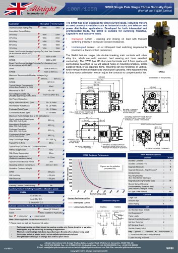
(Part of the SW80 Series)
100A/125A
Application
Interrupted
Uninterrupted
100A
125A
30% Duty
185A
230A
40% Duty
160A
200A
50% Duty
140A
175A
60% Duty
130A
160A
70% Duty
120A
150A
The DC92 has been designed for direct current loads, particularly motors as used on small
electric vehicles such as light industrial trucks. Developed for both interrupted and
uninterrupted loads, the DC92 is suitable for switching Resistive, Capacitive and Inductive
loads.
Thermal Current Rating (Ith)
Intermittent Current Rating:
•t
•t
800A at 48V
DC92B
800A at 80V
Maximum Recommended Contact Voltages (Ue):
DC92
48V D.C.
DC92B
96V D.C.
Typical Voltage Drop per pole
across New Contacts at 100A
40mV
Mechanical M.T.B.F
Uninterrupted current - no or infrequent load switching
requirements (maintains a lower contact resistance).
The DC92 features double breaking main contacts with silver
alloy tips, which are weld resistant, hard wearing and have excellent
conductivity. The DC92 is a monoblock construction, resulting in a
neat compact design which is compatible with modern electronic
control systems. The M8 stud main terminals can be configured
in a variety of ways in order to suit the application. Supplied with
a mounting bracket as standard, or alternatively supplied with M4
tapped holes. Mounting can be horizontal or vertical, when vertical
the M8 contact studs should point upwards. If the requirement is for
downwards orientation we can adjust the contactor to compensate
for this.
Rated Fault Current Breaking Capacity (Icn) 5ms Time Constant:
(in accordance with UL583*)
DC92
Interrupted current - opening and closing on load with frequent
switching (results in increased contact resistance).
DC92A
>5 x 10⁶
Coil Voltage Available (Us)
(Rectifier board required for A.C.)
From 6 to 240V D.C.
Coil Power Dissipation:
Highly Intermittent Rated Types
20 - 30 Watts
Intermittently Rated types
15 - 20 Watts
Prolonged Rated Types
13 - 15 Watts
Continuously Rated Types
7 - 13 Watts
Maximum Pull-In Voltage (Coil at 20˚ C) Guideline:
Highly Intermittent Rated types
(Max 25% Duty Cycle)
60% Us
Intermittently Rated types
(Max 70% Duty Cycle)
60% Us
Prolonged Operation
(Max 90% Duty Cycle)
60% Us
Continuously Rated Types
(100% Duty Cycle)
66% Us
Drop-Out Voltage Range
10 - 25% Us
Typical Pull-In Time
(N/O contacts to close)
20ms
Typical Drop-Out Time (N/O Contacts to Open):
5ms
50ms
8 - 20ms
- 40˚C to + 60˚C
+ 20 gms
+ 50 gms
5A
2A at 48V D.C.
Advised Connection Sizes for Maximum Continuous Current
Cable
Key:
400
Mounting Brackets
300
Magnetic Latching† (Not fail safe)
Closed Contact Housing‡
Environmentally Protected IP66
(see DC92P Catalogue sheet)
52mm2 [0.081inch2]
Contact Performance Key:
Interrupted Current
0
80
70
0
60
0
50
0
Current (Amperes)
= Uninterrupted
B
B
M
P
○
EE
○
○
T
Contacts
Large Tips
Connection Diagram
A
○
EE Type (Steel Shroud)
Textured Tips
Silver Plating
L
X
Coil
Uninterrupted Current
Rated suitable for Application
= Interrupted
0
0
0
0.5A at 240V D.C.
Copper busbar
Armature Cap
100
Auxiliary Contact Switching Capabilities (Resistive Load):
5A at 24V D.C.
○
○
○
●
○
○
Magnetic Blowouts - High Powered†
200
Auxiliary Details
Auxiliary Thermal Current Rating
X
Magnetic Blowouts†
500
40
With Blowouts
600
○
Auxiliary Contacts - V3
Figures are for guideline
purposes only
700
0
Per Auxiliary
Time (Seconds)
770 gms
Suffix
Auxiliary Contacts
800
Guideline Contactor Weight:
DC92
General
900
0
Operating Ambient Temperature
DC92 Available Options
DC92 Contactor Performance
3ms
10
Typical Contact Bounce Period
30
With Diode and Resistor
(Subject to resistance value)
Dimensions in mm [inches]
0
With Diode Suppression
20
Without Suppression
○
○
○
○
AC Rectifier Board (Fitted)
Coil Suppression†
Flying Leads
Note: Where applicable values shown are at 20˚C
Manual Override Operation
* Please check our web site for product UL status
M4 Stud Terminals
X
M5 Terminal Board
F
○
○
•t
•t
•t
•t
v1a-06-13
Performance data provided should be used as a guide only. Some de-rating or variation
from figures may be necessary according to application.
Thermal current ratings stated are dependant upon the size of conductor being used
For further technical advice email: technical@albrightinternational.com
Albright reserve the right to change data without prior notice
Vacuum Impregnation
Key: Optional
○
Standard
●
Not Available X
†
Connections become polarity sensitive
‡
Open Housing Available
Albright International Ltd, Evingar Trading Estate, Ardglen Road, Whitchurch, Hampshire, RG28 +44 UK
Albright International, 125 Red Lion Road, Surbiton, Surrey KT6 7QS, England,Tel: +44 (0) 20 8390 5357, Fax:7BB,(0) 20 8390 1927
Tel: sales@albrightinternational.com or technical@albrightinternational.com Web 890030, Fax: +44 (0)1256 890043
E-mail: +44 (0)1256 893060, Fax: +44 (0)1256 893562, Dedicated Sales Tel: +44 (0)1256 Site: www.albrightinternational.com
E-mail: sales@albrightinternational.com or technical@albrightinternational.com Web Site: www.albrightinternational.com
Copyright © 2010 Albright International Ltd
Copyright © 2013 Albright International LTD
DC92
"