عضویت
عضویت  ورود اعضا
 راهنمای خرید


Clamping Elements RCK 150 pages
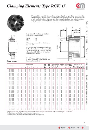
Clamping Elements Type RCK 15
Recommended tolerances for full
torque transmission are:Shaft
Hub
h8
H8
Clamping surfaces to be finished to
Rz ≤ 15 µm.
Fax: +44 121 325 1079
Cross & Morse can provide standard
Roller Chain Sprockets finish bored to
accommodate RCK 15 shaft clamping
elements, with ability to fit to either
hub or sprocket end.
X = Distance required to remove
screws, additional clearance for alan
key may be required.
Dimensions
Axial
Force
F
kN
Surface Pressure
Shaft
Hub
Ps
Ph
2
N/mm
N/mm2
d
D
L
L1
L2
L3
X
Torque
Cap.
M
Nm
RCK15-14x55
RCK15-16x55
RCK15-18x55
14
16
18
55
55
55
39
39
39
17
17
17
22
22
22
31
31
31
25
25
25
282
313
353
39
39
39
458
400
356
118
118
118
RCK15-19x55
RCK15-20x55
RCK15-22x55
19
20
22
55
55
55
39
39
39
17
17
17
22
22
22
31
31
31
25
25
25
372
392
431
39
39
39
337
320
290
RCK15-24x55
RCK15-25x55
RCK15-28x55
24
25
28
55
55
55
39
39
39
17
17
17
22
22
22
31
31
31
25
25
25
470
490
549
39
39
39
RCK15-30x55
RCK15-24x65
RCK15-25x65
30
24
25
55
65
65
39
39
39
17
17
17
22
22
22
31
31
31
25
25
25
588
617
637
RCK15-28x65
RCK15-30x65
RCK15-32x65
28
30
32
65
65
65
39
39
39
17
17
17
22
22
22
31
31
31
25
25
25
RCK15-35x65
RCK15-38x65
RCK15-40x65
35
38
40
65
65
65
39
39
39
17
17
17
22
22
22
31
31
31
RCK15-30x80
RCK15-32x80
RCK15-35x80
30
32
35
80
80
80
41
41
41
20
20
20
25
25
25
RCK15-38x80
RCK15-40x80
RCK15-42x80
38
40
42
80
80
80
41
41
41
20
20
20
RCK15-45x80
RCK15-48x80
RCK15-50x80
45
48
50
80
80
80
41
41
41
RCK15-40x80H
RCK15-45x80H
RCK15-50x80H
40
45
50
80
80
80
41
41
41
Dimensions mm
Part No.
Clamping Screws Approx.
Size
Torque Weight
Min. Hub Dia* mm
kg
Assy
Type A
Assy
Type B
Assy
Type C
M8
M8
M8
41
41
41
0.51
0.49
0.48
81
81
81
75
75
75
69
69
69
118
118
118
M8
M8
M8
41
41
41
0.47
0.47
0.45
81
81
81
75
75
75
69
69
69
265
255
228
118
118
118
M8
M8
M8
41
41
41
0.44
0.43
0.41
81
81
81
75
75
75
69
69
69
39
51
51
213
332
320
118
122
122
M8
M8
M8
41
41
41
0.40
0.68
0.63
81
97
97
75
89
89
69
82
82
725
764
823
51
51
51
285
267
250
122
122
122
M8
M8
M8
41
41
41
0.61
0.58
0.56
97
97
97
89
89
89
82
82
82
25
25
25
902
970
1029
51
51
51
228
210
200
122
122
122
M8
M8
M8
41
41
41
0.53
0.50
0.47
97
97
97
89
89
89
82
82
82
33
33
33
25
25
25
1082
1155
1260
72
72
72
315
298
272
120
120
120
M8
M8
M8
41
41
41
1.04
1.03
0.98
119
119
119
109
109
109
101
101
101
25
25
25
33
33
33
25
25
25
1370
1440
1510
72
72
72
250
238
226
120
120
120
M8
M8
M8
41
41
41
0.94
0.91
0.89
119
119
119
109
109
109
101
101
101
20
20
20
25
25
25
33
33
33
25
25
25
1620
1735
1806
72
72
72
212
198
190
120
120
120
M8
M8
M8
41
41
41
0.83
0.79
0.74
119
119
119
109
109
109
101
101
101
20
20
20
25
25
25
33
33
33
25
25
25
2157
2422
2700
108
108
108
340
302
272
169
169
169
M8
M8
M8
41
41
41
0.89
0.85
0.78
144
144
144
126
126
126
111
111
111
Email: sales@crossmorse.com
Nm
2
*Minimum outside diameter of hubs manufactured in medium carbon steels with yield strength ≥ 320 N/mm .
For hub types, and other materials, refer to page 3.
For assembly and disassembly instructions refer to page 24.
5
INDEX
BACK
NEXT
Te l : + 4 4 1 2 1 3 6 0 0 1 5 5
Designed for use with standardised ranges of pulleys, sprockets, and gears, the
shaft clamping elements can accommodate a large range of shaft diameters with
a hub of constant bore diameter. On clamping precise axial and radial positioning is provided, combined with medium torque transmission capability.