عضویت
عضویت  ورود اعضا
 راهنمای خرید


KE Couplings0 pages

KE Series Elastomeric Couplings
Te l : + 4 4 1 2 1 3 6 0 0 1 5 5
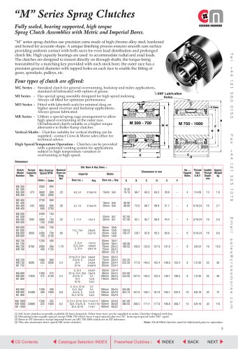
The KE coupling is a general-purpose flexible coupling, fully
interchangeable with the standard couplings frequently used
throughout the industry. The coupling consists of two machined
cast iron hubs connected by an elastomeric gear ring. Available in
8 basic sizes, with torque capacity to 3300 Nm, the KE coupling
provides positive power transmission between shafts, combined
with the ability to accommodate moderate levels of misalignment.
KE couplings are designed to transmit torques equal to the
capabilities of sizes of commercial shafting which can be
accommodated. Available either with parallel bore or with taper
bush, these couplings are quick and easy to assemble with the
machined outer flanges enabling simple alignment with just a
straight edge. The elastomeric gear ring is moulded in Pebax R
Polyether which is oil resistant, has a partial resistance to
chemicals, and a low moisture absorption rate. The gear ring
cushions transient peak torques, effectively reducing transmission
of operational vibrations and shock loads. Standard couplings can
be operated in environmental temperatures ranging from –40˚C
to +85˚C.
Refer to page 2 for standard procedure for coupling selection. The number of starts to which an KE coupling is subjected will
affect its life, and it is thus necessary to modify the design power Pd for drives subject to more than 4 starts per day by factor f. in
table, to get selection power Ps. Thus
No. starts/day
5-30
31-60
60+
f.
Ps = Pdf
1.2
1.3
1.5
Fax: +44 121 325 1079
KE Coupling Selection Procedure
kW Power Ratings - Standard KE Couplings
Coupling SIze
7
9
11
13
15
18
23
28
100*
200
0.35
0.69
0.88
1.75
1.75
3.52
3.44
6.88
6.59
13.18
10.43
20.86
22.00
44.02
34.65
69.30
400
600
800
1.39
2.08
2.78
3.51
5.25
7.00
7.04
10.55
14.07
13.77
20.65
27.53
26.37
39.55
52.73
41.72
62.58
84.44
88.04
132.06
176.08
138.60
207.90
277.20
1000
1200
1400
3.47
4.16
4.86
8.75
10.50
12.25
17.59
21.11
24.62
34.42
41.30
48.18
65.92
79.10
92.28
104.30
125.20
146.02
220.10
264.12
308.13
346.50
415.80
485.10
1600
1800
2000
5.55
6.25
6.94
14.00
15.76
17.51
28.14
31.66
35.18
55.07
61.95
68.83
105.47
118.65
131.83
166.88
187.74
208.60
352.15
396.17
440.19
554.10
623.70
693.00
2200
2400
2600
7.64
8.33
9.02
19.26
21.00
22.76
38.69
42.21
45.73
75.72
82.60
89.48
145.01
158.20
171.38
229.46
250.32
271.18
484.21
528.23
572.25
762.30
–
2800
3000
3500
9.72
10.41
12.15
24.51
26.26
30.64
49.25
52.76
61.56
96.37
103.25
120.46
184.57
197.75
230.71
292.04
312.90
4000
4500
5000
13.88
15.62
17.35
35.01
39.39
43.76
70.35
79.14
87.94
137.67
5500
6000
6500
19.09
20.82
22.56
48.14
52.52
7000
7500
24.30
26.03
)
)
)
)
)
)
Dynamic balancing required
for shaft speeds over
3600 rpm
)
)
*For shaft speeds below 100 rpm use nominal torque Tn.
Maximum shaft speeds of coupling controlled by safe max. peripheral speed for cast iron.
6
INDEX
BACK
NEXT
Email: sales@crossmorse.com
Shaft Speed
rpm