عضویت
عضویت  ورود اعضا
 راهنمای خرید


SP 20000 pages

SPACEPAK™ SERIES
SP 2000
Description
ᔢ
ᔢ
ᔢ
ᔢ
ᔢ
ᔢ
ᔢ
ᔢ
ᔢ
ᔢ
Operation mode and max sensing range:
Thru-beam: 0-45 m
Retro reflective: 0,1-12 m
Polarised retro reflective: 0,1-10 m
Diffuse proximity: 0-3 m
Background suppression: 0-1,5 m
Compact rectangular housing (50x50 mm)
Cable or rotatable plug connection
Sensitivity adjustment via potentiometer
Switch selectable light or dark function
Adjustable on/off time delay
Power, output and signal level indicators
10-30 V dc or 12-240 V ac/dc supply voltage
4 wire, NPN/PNP output or 5 wire relay output
Test input
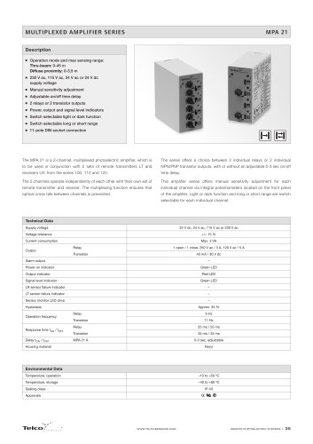
The SP 2000 series consists of a self-contained transmitter SPT and
The test input in the 10-30 V dc, SPT is intended to be used for disabling
receiver SPR, which are to be used in thru-beam mode, SPRR for retro-
or enabling the transmitter power temporarily for test purposes or for
reflective, SPPR for polarised retro-reflective, an SPP for diffuse proximity
multiplexing applications.
and SPBS for background suppression. All are offered with sensitivity
adjustment
via
integral
potentiometer
with
either
cable
The dc series is protected against reverse polarity of power supplies, test
or
input and output signals. The output is protected against short circuit
180º rotatable plug connection.
and inductive loads.
The complete series is available either as a 4 wire, NPN/PNP transistor
output with 10-30 V dc supply voltage or as a 5 wire, relay output with a
12-240 V ac/dc supply voltage both offering switch selectable light or
dark function and potentiometer adjustable 0 -10 sec on/off time delay.
Technical Data
SPT
Supply voltage
SPR
ac / dc
SPRR
SPPR
dc
+/– 15 %
Relay
–
Transistor
–
Reverse polarity protected
Short circuit protected
dc
1 open / 1 close, 240 V ac / 2 A
200 mA / 30 V dc
dc
Current consumption
Yes
–
Yes
ac
< 70 mA
dc
< 65 mA
Response time tON / tOFF
ac
–
25 Hz
dc
Maximum operation frequency
SPBS
10-30 V dc
Voltage ripple
Output
SPP
12-240 V dc / 20-240 V ac
–
250 Hz
ac
–
20 ms / 20 ms
dc
–
2 ms / 2 ms
–
0-10 sec, adjustable
Delay tON / tOFF
Power on indicator
Green LED
Output indicator
–
Signal status indicator
–
Hysteresis
–
Yellow LED
Red LED
20-30 %
Approx. 10 %
Opening angle
–
+/– 2,5°
+/– 1,5°
+/– 5°
Emission angle
+/– 2°
–
+/– 2°
+/– 1,5°
Housing material
Sensor housing
Infrared
(880 nm)
Polycarbonate / ABS
Front lens
Cable, PVC Ø 4,9 mm
Visible Red
(670 nm)
3-10 %
–
Light source
Infrared
(880 nm)
5-15 %
Infrared
(880 nm)
Polycarbonate
ac
2 x 0,20 mm2
5 x 0,20 mm2
dc
3 x 0,20 mm2
4 x 0,20 mm2
WWW.TELCOSENSORS.COM
SELF-CONTAINED PHOTOELECTRIC SYSTEMS
I 99
"