عضویت
عضویت  ورود اعضا
 راهنمای خرید


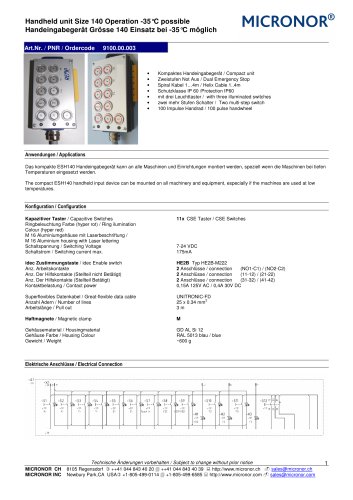
MR320 Controller for all fiber optic incremental encoder0 pages

MR320
Controller Modul for fiber optical incremental Encoder
Auswertmodul für den faser optischen inkremental Drehgeber
Art.Nr. / PNR / Ordercode
9350.01.180
•
•
•
•
•
•
•
•
•
Auswertgerät für alle Fiber optischen Drehgeber/ Controller module for all Fiber optic incremental Encoder
DIN Montage / Mounting on 35mm DIN Rail
Gehäuse aus Aluminium / Body anodized Aluminium
Speisespannung +15VDC ….32VDC / Operates from 15VDC to 32VDC
Schnittstelle A/B Quadrature, Analoge 4-20mA, +-10V / Interface A/B quadrature, line driver and Push Pull
and 4-20mA and +-10V
USB Schnittstelle mit Modbus RTU oder RS422/485 Seriel / USB,Modbus RTU or RS422/RS485 serial
interface
Temperaturebereich -5°C …. 55°C / Temperature -5°C…..55°C
Schutzgrad IP 40 / Protection IP 40
Stecker LC Duplex / optical Connector LC Duplex
Anwendungen / Applications
The MR320 Controller module is the active half of the MR320 series Fiber Optic Incremental Encoder System. The module incorporates multiple built-in
interfaces for compatibility with PLCs, motor drives and other motion control systems.
The MICRONOR fiber optical rotary encoder system is used in MRI systems, rail technology, in the oil industry, in mines and Steelproduktion but also in
various research laboratories.
Das MR320 Auswertgerät ist der aktive Teil vom MICRONOR Fiber optischen incremental Drehgebersystem. Das Modul wandelt die optischen Signale vom
Drehgeber in die bekannten elektrischen Signale wie A/B TTL, 4-20mA oder +-10V.
Das MICRONOR Fiber optische Drehgebersystem wird in MRI-Systemen, in der Bahntechnik, in der Oelindustrie, in Minene und Stahlverarbeiteung aber
auch in verschiedenen Forschungslabors eingesetzt.
Spezifikation / Specifications
Functional and Electrical Interface
DIRECT Quadrature Outputs
Bandwidth
Format
POSITION COUNTER Range
DIVIDER Quadrature Outputs
Analog Outputs
Current Output:
Voltage Output:
RS422/485 Interface
RS232 Interface
Modbus interface
USB interface
Electrical Connections
70kHz max. (Contact Micronor concerning modifications for higher bandwidth applications.)
A/B Push-Pull and A/A’/B/B’ RS422 Line Driver
Direction/Sign Bit plus 24-bit counter value (±8,388,607, equivalent to 8,192 revolutions with MR324
1024ppr encoder). Both software and hardware Zero (calibration) Set available.
DIVIDER range is 2-128. A/A’/B/B’ Line Driver (A/B Push-Pull available as option,)
Each output is individually programmable for POSITION (full-scale range of 1-8,388,607 counts) or SPEED
(full-scale range of 10-10,000 RPM)
Range: 0mA to 24mA, Max Burden Resistance: 500Ω (24V supply)
Range: ±12V; Max Current: 5mA (2kΩ load); Short Circuit < 5 seconds
Direct connection via J3, also Modbus (RTU) compatible)
With optional MR232-1 Converter Cable
Modbus (RTU) compatible RS422/RS485 interface
USB, disables RS485/Modbus interface when used
J1, J2 J3 connections via WAGO QuickConnect Plugs (supplied with MR320)
Fiber Optic Interface
Connector Type
Duplex LC plug with Super PC Polish
Performance Requirements: IL<0.5dB, RL>24dB, Telecordia GR-326 Endface Geometry
2 x Multimode 62.5/125, Graded Index, 0.275NA
Fiber Type
Maximum Optical Link Length
Maximum of 2500 meters (8300 ft) or 2-way optical loss of 12.5dB at 850nm
(Contact Micronor for longer distance requirements)
Power Supply
Power Supply Input
+5V Output
MICRONOR CH
MICRONOR INC
+15VDC to +32VDC, 60mA (During Power Up, power supply should be capable of delivering a momentary
current in excess of 100mA.)
10mA maximum load. (Designed for powering MR232-1 RS485/RS232 adapter cable)
Technische Änderungen vorbehalten / Subject to change without prior notice
8105 Regensdorf
++41 044 843 40 20 ++41 044 843 40 39
http://www.micronor.ch
Newbury Park,CA USA +1-805-499-0114 +1-805-499-6585
http://www.micronor.com
1
sales@micronor.ch
sales@micronor.com