عضویت
عضویت  ورود اعضا
 راهنمای خرید


QSR0 pages

96
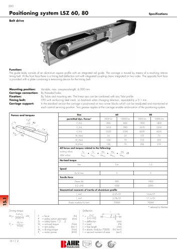
Positioning system QSR 60, 80, 100, 125
Specifications
6.1
Rail guide
Function:
This unit consists of a square aluminium profile with an integrated ball rail. This unit can be driven by a pneumatic cylinder or other additional
drives or it serves as a load carrying slide unit.
Fitting position:
Carriage mounting:
Unit mounting:
Carriage support:
As required. Max. length 6.000 mm without joints.
By T-slots.
By T-slots and mounting sets. The linear axis can be combined with any T-slot profile.
In the standard version, the carriage runs on two runner blocks which can be adjusted and serviced at a
central servicing position. For longer carriages the number of runner blocks can be increased.
Size
Forces and torques
Fz
60
80
100
125
permitted dyn. forces*
5000 km
10000 km
5000 km
10000 km
5000 km
10000 km
5000 km
Fx (N)
-
-
-
-
-
-
-
-
Fy (N)
1410
990
3570
2550
4080
2900
6892
5470
13659
Mz
10000 km
Fy
Fz (N)
My
2500
8500
6050
10300
7270
17205
33
23
107
75
142
101
288
228
My (Nm)
Fx
3520
Mx (Nm)
104
73
310
222
439
311
1110
881
Mz (Nm)
Mx
100
70
296
210
412
292
1012
803
All forces and torques related to the following:
existing values
Fy
table values
Fydyn
+
Fz
Fzdyn
Mx
+
Mxdyn
+
My
Mydyn
+
Mz
Mzdyn
≤1
Speed
(m/s) max
5
5
5
5
Geometrical moments of inertia of aluminium profile
lx mm4
4,3x10⁵
16,5x10⁵
43,0x10⁵
74,9x10⁵
ly mm
4,8x10
18,7x10
48,8x10
106,5x10⁵
Elastic modulus N/mm²
70000
70000
70000
70000
4
5
5
5
* referred to life-time
Deflection:
f=
F*L
E*I*192
f =
F=
L=
E=
I =
deflection
load
free length
elastic modulus 70000
second moment of area
3
6.1 | 10
(mm)
(N)
(mm)
(N/mm