عضویت
عضویت  ورود اعضا
 راهنمای خرید


CLOGGING INDICATORS0 pages

SUMMING-UP
CLOGGING
INDICATORS
DESCRIPTION
During the system operation, the
pressure drop through the lter
increases as the element clogs, due to
the contaminant retained.
The lter element must be replaced
when clogged and anyway before the
pressure drop reaches the bypass valve
set value.
For this reason it is recommended
a clogging indicator on the lter. It
gives a visual or electrical indication
and must have a set value lower than
the bypass valve set value, to get an
exact indication of the right time for
lter element replacement.
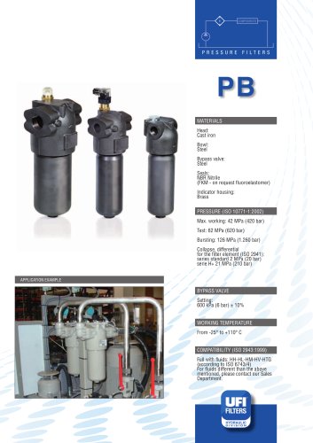
PRESSURE FILTERS
INDICATORS
Pressure gauges
Pressure switches
Differential, visual
Differential, electrical
Differential, el. + LED
Differential, el. + thermostat
Differential, el. + visual
Differential, el. Vandal proof
Differential, el. ATEX
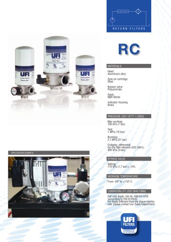
RETURN FILTERS
INDICATORS
Pressure gauges
Pressure switches
Differential, visual
Differential, electrical
Differential, el. + LED
Differential, el. + thermostat
Differential, el. + visual
Differential, el. ATEX
OFF-LINE FILTERS
INDICATORS
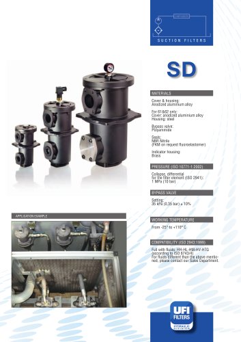
SUCTION FILTERS
INDICATORS
Differential, visual
Differential, electrical
Differential, el. + LED
Differential, el. + thermostat
Differential, el. + visual
Differential, el. ATEX
Vacuum gauges
Vacuum switches
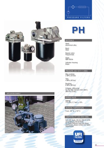
On return and low pressure lters the
clogging indicator can be a pressure
gauge or a pressure switch, measuring
the pressure upstream the lter.
On some return lters and on high
pressure lters, the clogging indicator
can be of differential type: measuring
the pressure upstream and downstream
the lter and activating a signal when
the differential pressure reaches the set
value.
On suction lters the clogging indicator
is a vacuum gauge or a vacuum switch,
measuring the depressure downstream
the lter.
All the UFI lters have the port for the
indicator as a standard feature; if the
lter is ordered without indicator the
port is plugged with
a removeable plug allowing the
indicator to be added easily at any time.