عضویت
عضویت  ورود اعضا
 راهنمای خرید


Vibration Eliminators0 pages
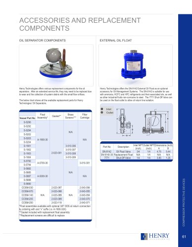
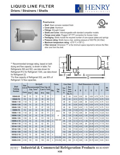
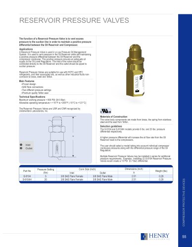
VIBRATION ELIMINATORS
The function of a Vibration Eliminator is to absorb compressor
vibration to reduce the risk of damage to system equipment and
pipework.
Applications
A Vibration Eliminator can be installed in both the suction and discharge lines
of air-conditioning and refrigeration systems. Each unit is constructed of a
deep pitch corrugated hose covered with a stainless steel braid. The hose
and braid are reinforced by ferrules at each end and connected to copper
tube ends by a high temperature braze alloy.
Vibration Eliminators are suitable for use with HCFC and HFC refrigerants
and their associated oils, as well as other industrial fluids non-corrosive to
stainless steel and copper.
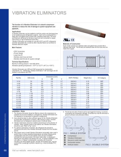
Materials of Construction
Each model consists of a stainless steel corrugated hose covered with a
stainless steel braid. The ferrules are stainless steel and the tube ends are
made from copper.
Main Features
Ÿ
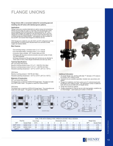
ODS Connections
Ÿ
Proven Design
Ÿ
Large hose ID
Ÿ
Stainless steel hose and braid
Ÿ
Stainless steel ferrules for superior strength
ØB
ØB
C
C
Technical Specifications
Maximum working pressure = see table below
Allowable operating temperature = -40°F to +212°F (-40°C to +100°C)
A
Vibration Eliminators are USR and CNR recognized by Underwriters
Laboratories, Inc. Additionally, Vibration Eliminators 1-3/8” and larger are CE
marked in accordance with PED.
Part No
ODS (inch)
V-1/4
V-3/8
V-1/2
V-5/8
V-3/4
V-7/8
V-1-1/8
V-1-3/8
V-1-5/8
V-2-1/8
V-2-5/8
V-3-1/8
V-3-5/8
V-4-1/8
1/4
3/8
1/2
5/8
3/4
7/8
1-1/8
1-3/8
1-5/8
2-1/8
2-5/8
3-1/8
3-5/8
4-1/8
A
8.0
8.6
9.0
9.9
10.6
12.0
13.1
15.6
16.9
20.6
24.3
26.9
32.2
33.0
Dimensions (inch)
ØB
0.6
0.7
0.9
1.0
1.1
1.3
1.5
1.8
2.2
2.7
3.4
4.2
5.2
5.2
COMPRESSOR PROTECTIVE DEVICES
Installation - Notes
68
1. The Vibration Eliminator should be fitted as close to the compressor as
possible and must be installed in a straight line. Vibration Eliminators are
not designed to compensate for pipework misalignment.
2. Care should be taken to allow sufficient space for the Vibration Eliminator
to avoid static compression or tension, after brazing in place. Vibration
Eliminators are not designed to absorb axial or torsional stress.
3. Vibration Eliminators should be installed perpendicular to the direction of
vibration. When vibration exists in two planes, two Vibration Eliminators
should be used. Refer to Fig 1 and 2.
4. For optimum absorption of vibration, the refrigerant line should be
anchored at the end of the Vibration Eliminator furthest from the vibration
source.
5. Take special care to install Vibration Eliminators horizontally when used in
suction lines or where operating temperatures are below freezing point.
Condensation may form on the outside of the unit and if installed
vertically this may accumulate in the lower braid collar. In subsequent
freezing this may deform and destroy the unit. If vertical installation is the
only option, or indeed if condensation is possible with horizontal
mounting, the entire flexible section, ferrules and braided hose, must be
covered with a watertight synthetic material e.g. a heat shrinkable PVC
sleeve.
Visit our website: www.henrytech.com
MWP (PSI/Bar)
Weight (lbs.)
CE Category
500/34.5
500/34.5
500/34.5
500/34.5
500/34.5
500/34.5
500/34.5
500/34.5
500/34.5
390/26.9
339/23.4
300/20.7
175/12.0
175/12.0
C
0.7
0.7
0.7
0.9
1.1
1.2
1.5
1.6
2.0
2.4
3.0
3.3
3.9
4.3
0.15
0.26
0.31
0.44
0.51
0.62
0.88
1.39
1.98
2.76
5.29
8.71
13.23
14.77
SEP
SEP
SEP
SEP
SEP
SEP
SEP
Cat I
Cat I
Cat I
Cat I
Cat I
Cat I
Cat I
6. The ferrule and start of braid must be wet-ragged for brazing, to prevent
overheating and subsequent damage. All excess flux must be removed to
prevent corrosion and premature failure.
1
1
5
4
2
3
2
5
FIG 1 - SINGLE SYSTEM
ΠCompressor
Vibration Eliminator
2
3
Ž Secure to solid member
Horizontal motion
Vertical motion
FIG 2 - DOUBLE SYSTEM