عضویت
عضویت  ورود اعضا
 راهنمای خرید


ROOTSâ„¢ DVJ WHISPAIRâ„¢ Dry Vacuum Exhauster0 pages
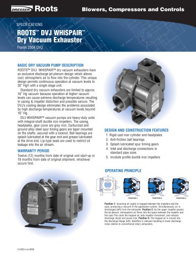
NEO-PHS Series (Europe)vol 2.indd table.main {} tr.row {} td.cell {} div.block {} div.paragraph {} .font0 { font:5.00pt "Arial", sans-serif; } .font1 { font:6.00pt "Arial", sans-serif; } .font2 { font:7.00pt "Arial", sans-serif; } .font3 { font:8.00pt "Arial", sans-serif; } .font4 { font:9.00pt "Arial", sans-serif; } .font5 { font:10.00pt "Arial", sans-serif; } .font6 { font:21.00pt "Arial", sans-serif; } .font7 { font:22.00pt "Arial", sans-serif; } fzz^&zzf Roots Blowers, Compressors and Controls ROOTS DVJ WHISPAPٙ Dryr Vficilum Exhau BASIC DRY VACUUM PUMP DESCRIPTION ROOTS DVI WHISPAIRٙ dry vacuum exhausters have an exclusive discharge jet plenum design which allows cool, atmospheric air to flow into the cylinder. This unique design permits continuous operation at vacuum levels to 20" HgV with a single stage unit. Standard dry vacuum exhausters are limited to approx. 16" Hg vacuum because operation at higher vacuum levels can cause extreme discharge temperatures resulting in casing & impeller distortion and possible seizure. The DVI's cooling design eliminates the problems associated by high discharge temperatures at vacuum levels beyond 16" Hg. DVI WHISPAIR vacuum pumps are heavy-duty units with integral-shaft ductile iron impellers. The casing, headplates, gear cover are grey iron. Carburized and ground alloy steel spur timing gears are taper mounted on the shafts, secured with a locknut. Ball bearings are splash lubricated at the gear end and grease lubricated at the drive end. Lip-type seals are used to restrict oil leakage into the air stream. WARRANTY PERIOD Twelve (12) months from date of original unit start-up or 18 months from date of original shipment, whichever occurs first. DESIGN AND CONSTRUCTION FEATURES 1. Rigid cast iron cylinder and headplates 2. Anti-friction ball bearings 3. Splash lubricated spur timing gears 4. Inlet and discharge connections in standard pipe sizes 5. Involute profile ductile iron impellers OPERATING PRINCIPLE POSITION 1 POSITION 2 POSITION 3 Position 1: Incoming air (right) is trapped between the impellers and the case, producing a vacuum in the application system. Simultaneously, air is discharged (left) from the exhauster. Position 2: As the upper impeller passes the jet plenum, atmospheric airflows into the space between the impeller and the case.This cools the trapped air, aids impeller movement, and reduces discharge shock and power loss. Position 3: The trapped air is moved into the discharge flange (left). Backflow is reduced resulting in lower discharge noise relative to conventional rotary exhausters. S-5582.A rev.0608
"