عضویت
عضویت  ورود اعضا
 راهنمای خرید


Silicon Designs Model 2240 Hermetically Sealed Analog Accel with Removable Plug & Cable0 pages
SILICON DESIGNS, INC.
Model 2240
Advanced Accelerometer Solutions
Hermetic Analog Accelerometer Module
Hermetically Sealed Titanium Case
Detachable Cable (sold separately)
Capacitive Micromachined
Nitrogen Damped
±4V Differential Output or 0.5V to 4.5V Single
Ended Output
Fully Calibrated
Low Power Consumption
-55 to +125°C Operation
+9 to +32V DC Power
Simple Four Wire Connection
Low Impedance Outputs Will Drive Up To 50 Feet
of Cable
Responds to DC and AC Acceleration
Non Standard g Ranges Available
Low Noise
Serialized for Traceability
Available Cables
Cable
Cable
Length
Model Number
4 ft
2240-CAB-04
14 ft
2240-CAB-14
33 ft
2240-CAB-33
50 ft
2240-CAB-50
Available G-Ranges
Model
Full Scale
Number
Acceleration
±2g
2240-002
±5g
2240-005
± 10 g
2240-010
± 25 g
2240-025
± 50 g
2240-050
±100 g
2240-100
±200 g
2240-200
±400 g
2240-400
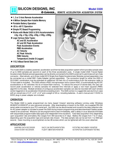
DESCRIPTION
The model 2240 accelerometer is a hermetically sealed version of the model 2220. This rugged module combines an
integrated model 1221L accelerometer with high drive, low impedance buffering for measuring acceleration in
commercial/industrial environments. It is tailored for zero to medium frequency instrumentation applications. The
titanium case is sealed using a laser welding process and is easily mounted via two #4 (or M3) screws. On-board
regulation is provided to minimize the effects of supply voltage variation. It is relatively insensitive to temperature
changes and gradients. A model 2240-CAB cable, sold separately (see order information above), connects via a
miniature 4-pin screw-on connector. The cable’s shield is electrically connected to the titanium case while the
ground (GND) wire is isolated from the case. An initial calibration sheet (2240-CAL) is included and periodic
calibration checking is available.
OPERATION
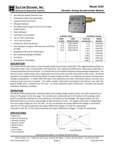
The Model 2240 accelerometer module produces two analog voltage outputs, which vary with acceleration as
shown in the graph on the next page. The sensitive axis is perpendicular to the bottom of the package, with
positive acceleration defined as a force pushing on the bottom of the package. The signal outputs are fully
differential about a common mode voltage of approximately 2.5 volts. The output scale factor is independent
from the supply voltage of +9 to +32 volts. At zero acceleration the output differential voltage is nominally 0
volts DC; at "full scale acceleration the output differential voltage is "4 volts DC respectively.
nominally 0 volts DC; at "full scale acceleration the output differential voltage is "4 volts DC respectively.
5
OUTPUT VOLTAGE
APPLICATIONS
• Flight Tests
• Vibration Monitoring
• Vibration Analysis
• Machine Control
• Modal Analysis
• Robotics
• Crash Testing
• Instrumentation
4
AO
N
P
AO
3
2
1
0
-Full Scale
0
+ Full Scale
ACCELERATION
SPECIFICATIONS SUBJECT TO CHANGE WITHOUT NOTICE
th
Silicon Designs, Inc. • 13905 NE 128 Street, Kirkland WA 98034 • Phone: 425-391-8329 • Fax: 425-391-0446
www.silicondesigns.com
[page 1]
September 2012